
Loose Leaf for Engineering Circuit Analysis Format: Loose-leaf
9th Edition
ISBN: 9781259989452
Author: Hayt
Publisher: Mcgraw Hill Publishers
expand_more
expand_more
format_list_bulleted
Concept explainers
Videos
Textbook Question
Chapter 8, Problem 57E
For the circuit represented in Fig. 8.82, (a) obtain an expression for v which is valid for all values of t; (b) sketch your result for 0 ≤ t ≤ 3 s.
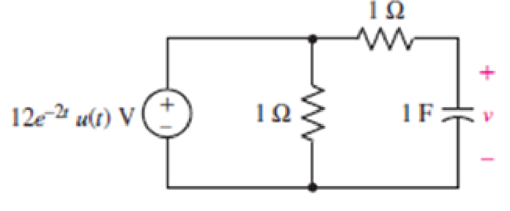
FIGURE 8.82
Expert Solution & Answer
Want to see the full answer?
Check out a sample textbook solution
Students have asked these similar questions
The switch in the circuit in Figure 8 changes position from position b to position a at t=0a) Find and plot vc(t)fort≥0.b) Find i1(t)for t>0c) Find i(t)for t>0d) Find v(t)for t>0.
2.
8.23 For the network in Fig. 8.76, what value of C is
needed to make the response underdamped with
unity damping factor (a = 1)?
10 Ω
20 mH
C= 10 mF
For the equation of current described below, determine 1) characteristic equation, 2) type of damping
3) i(t), take and i(0) = 1 and di(0)/dt = 2
di²
di
+10i(t) = 0
Chapter 8 Solutions
Loose Leaf for Engineering Circuit Analysis Format: Loose-leaf
Ch. 8.1 - For the circuit in Fig. 8.2, what value of...Ch. 8.1 - Noting carefully how the circuit changes once the...Ch. 8.2 - In a source-free series RC circuit, find the...Ch. 8.3 - Prob. 4PCh. 8.3 - Prob. 5PCh. 8.4 - Prob. 6PCh. 8.4 - Prob. 7PCh. 8.4 - Prob. 8PCh. 8.5 - Evaluate each of the following at t = 0.8: (a)...Ch. 8.6 - For the circuit of Fig. 8.37, find vc(t) at t...
Ch. 8.7 - Prob. 11PCh. 8.7 - The voltage source 60 40u(t) V is in series with...Ch. 8.7 - Prob. 13PCh. 8.8 - Prob. 14PCh. 8.8 - Prob. 15PCh. 8 - A source-free RC circuit has R = 4 k and C = 22 F,...Ch. 8 - A source-free RC circuit has v(0) = 12 V and R =...Ch. 8 - The resistor in the circuit of Fig. 8.51 has been...Ch. 8 - Prob. 4ECh. 8 - Prob. 5ECh. 8 - Prob. 6ECh. 8 - Prob. 7ECh. 8 - Prob. 8ECh. 8 - Prob. 9ECh. 8 - The switch in Fig. 8.56 has been closed for a long...Ch. 8 - For the circuit in Fig. 8.56, find (a) the total...Ch. 8 - Design a capacitor-based circuit that can achieve...Ch. 8 - (a) Graph the function f (t) = 10e2t over the...Ch. 8 - The current i(t) flowing through a 1 k resistor is...Ch. 8 - Radiocarbon dating has a similar exponential time...Ch. 8 - For the circuit of Fig. 8.4, compute the time...Ch. 8 - Design a circuit which will produce a current of 1...Ch. 8 - Prob. 18ECh. 8 - Prob. 19ECh. 8 - Referring to the circuit shown in Fig. 8.11,...Ch. 8 - Prob. 21ECh. 8 - With the assumption that the switch in the circuit...Ch. 8 - The switch in Fig. 8.57 has been closed since...Ch. 8 - The switch in the circuit of Fig. 8.58 has been...Ch. 8 - Assuming the switch initially has been open for a...Ch. 8 - (a) Obtain an expression for v(t), the voltage...Ch. 8 - For the circuit of Fig. 8.61, determine ix, iL,...Ch. 8 - Prob. 28ECh. 8 - Prob. 29ECh. 8 - Prob. 30ECh. 8 - Prob. 31ECh. 8 - (a) Obtain an expression for vx as labeled in the...Ch. 8 - Prob. 33ECh. 8 - Prob. 34ECh. 8 - Prob. 35ECh. 8 - Prob. 36ECh. 8 - Prob. 37ECh. 8 - The switch in Fig. 8.70 is moved from A to B at t...Ch. 8 - Prob. 39ECh. 8 - Prob. 40ECh. 8 - Evaluate the following functions at t = 1, 0, and...Ch. 8 - Prob. 42ECh. 8 - Prob. 43ECh. 8 - Prob. 44ECh. 8 - You can use MATLAB to represent the unit-step...Ch. 8 - With reference to the circuit depicted in Fig....Ch. 8 - For the circuit given in Fig. 8.75, (a) determine...Ch. 8 - Prob. 48ECh. 8 - Prob. 49ECh. 8 - You build a portable solar charging circuit...Ch. 8 - The switch in the circuit of Fig. 8.78 has been...Ch. 8 - The switch in the circuit of Fig. 8.78 has been...Ch. 8 - Prob. 53ECh. 8 - Prob. 54ECh. 8 - Prob. 55ECh. 8 - For the circuit represented in Fig. 8.82, (a)...Ch. 8 - Prob. 58ECh. 8 - Prob. 59ECh. 8 - For the circuit given in Fig. 8.85, (a) determine...Ch. 8 - The circuit depicted in Fig. 8.86 contains two...Ch. 8 - Prob. 62ECh. 8 - Prob. 63ECh. 8 - A series RL circuit has a voltage that steps from...Ch. 8 - For the two-source circuit of Fig. 8.89, note that...Ch. 8 - (a) Obtain an expression for iL as labeled in Fig....Ch. 8 - Obtain an expression for i(t) as labeled in the...Ch. 8 - Obtain an expression for i1 as indicated in Fig....Ch. 8 - Plot the current i(t) in Fig. 8.93 if (a) R = 10 ;...Ch. 8 - A dc motor can be modeled as a series RL circuit...Ch. 8 - Prob. 71ECh. 8 - Prob. 72ECh. 8 - A series RC sequentially switched circuit has R =...Ch. 8 - Refer to the circuit of Fig. 8.95, which contains...Ch. 8 - In the circuit of Fig. 8.95, a 3 mF capacitor is...Ch. 8 - Prob. 78E
Knowledge Booster


Learn more about
Need a deep-dive on the concept behind this application? Look no further. Learn more about this topic, electrical-engineering and related others by exploring similar questions and additional content below.Similar questions
- In the circuit shown in the figure, the switch is closed for a long time and is opened at t = 0. According to this:(a) Find i(0+) and v(0+).(b) Find (di(0+))/dt(c) Find i(t) for t>0.arrow_forward8.4 Step-Response Series RLC Circuits (3) Example 4 Having been in position for a long time, the switch in the circuit below is moved to position b at t = 0. Find v(t) and vR(t) for t > 0. 2.5 H 10Ω a ww- 12 V 22 10 V • Please refer to lecture or textbook for more detail elaboration. Answer: v(t) = {10 + [(-2cos3.464t – 1.1547sin3.464t)e-2t]} V VR(t)= [2.31sin3.464t]e-2t V 15 -19 wwarrow_forwardThe switch in the circuit shown has been in position a for a longtime. At t=0, it moves to position b. Find vC(t) for t≥0 2. 8.8 Find i(t) for t≥0 for the circuit Repeat if the 80 Ω resistor isreplaced by a 100 Ω resistorarrow_forward
- öialg äbäi A series RLC circuit has L=2H and C=0.25. The value of R that will produce unity * damping factor a is 0.5 ohm 4 ohm 2 ohm O 1 ohm نقطة واحدة you have to satisfy a condition to operate at * overdamped case which is a wo a = woarrow_forwardQ4 Calculate the voltage, vo (t) of the circuit shown in Figure Q4 for t>0 s.arrow_forwardObtain an equation which describes the behavior of iA as labeled in Fig. 8.88 over the range of −1 ms ≤ t ≤ 5 ms.arrow_forward
- Figure 8 showsa resistor inductor capacitor (RLC) circuit. The input to the system is the voltage v(t) and the output of the circuit is the current iz (t). 8 R, i(t) iz(t) v(t) Ve(t) R2 Figure 8 a) Determine differential equations containing i, (t), iz (t) and v. (t) for the appropriate meshes and nodes. b) Assuming zero initial conditions i) derive Laplace transformations of the differential equations found in a) ii) determine the transfer function G(s) = I2(s) VIs where l2(s) = L{i2 (t}} and V(s) = L{v(t}.arrow_forwardQuestion 8 Refer to the circuit below. The contribution due to the 2cos(1000t) A source in finding v(t) is : 100 p 2 con(1000) Aarrow_forwardLeft image: calculate V and i for t>0, if the circuit is in steady state at t=0- Right image: calculate i for t>0, if the circuit is in steady state at t=0-arrow_forward
- calculations. M ", =-8 sin (3t + 30°) V c) Solve the circuit in Figure Q3 for (1) and i(t) to show that i(1) leads v(1) by 90°. Show all of your 5 UTM 5 UTM 8 UTM 6 UTM 5 UTM 8 UTM UTM 8 UTM 8 UTM UTM 5 UTM 5 UTM UTM M 8 UTM 8 UT UTM 8 UTM 5 UTM 8 UTM 0.2 F . 5 UTM 8 UT UTM 5 UTM 5UTM TM 5 UTM 5 UT 5 UTM 5 UTM 5 UTarrow_forwardThe parameter values for the circuit are as follows: R=1 kΩ, L=12.5 H, C=2 μF, and Idc=30 mA.1. Find vo(t) for t≥0.2. Find io(t) for t≥0.3. Does your solution for io(t) make sense when t=0? Explain.arrow_forwardAssume that the switch in the circuit has been in the on position for a long time before switchinginstantaneously to the off position at t=0. Find vo(t) for t≥0arrow_forward
arrow_back_ios
SEE MORE QUESTIONS
arrow_forward_ios
Recommended textbooks for you
 Introductory Circuit Analysis (13th Edition)Electrical EngineeringISBN:9780133923605Author:Robert L. BoylestadPublisher:PEARSON
 Delmar's Standard Textbook Of ElectricityElectrical EngineeringISBN:9781337900348Author:Stephen L. HermanPublisher:Cengage Learning
 Programmable Logic ControllersElectrical EngineeringISBN:9780073373843Author:Frank D. PetruzellaPublisher:McGraw-Hill Education
 Fundamentals of Electric CircuitsElectrical EngineeringISBN:9780078028229Author:Charles K Alexander, Matthew SadikuPublisher:McGraw-Hill Education
 Electric Circuits. (11th Edition)Electrical EngineeringISBN:9780134746968Author:James W. Nilsson, Susan RiedelPublisher:PEARSON
 Engineering ElectromagneticsElectrical EngineeringISBN:9780078028151Author:Hayt, William H. (william Hart), Jr, BUCK, John A.Publisher:Mcgraw-hill Education,
Introductory Circuit Analysis (13th Edition)
Electrical Engineering
ISBN:9780133923605
Author:Robert L. Boylestad
Publisher:PEARSON
Delmar's Standard Textbook Of Electricity
Electrical Engineering
ISBN:9781337900348
Author:Stephen L. Herman
Publisher:Cengage Learning
Programmable Logic Controllers
Electrical Engineering
ISBN:9780073373843
Author:Frank D. Petruzella
Publisher:McGraw-Hill Education
Fundamentals of Electric Circuits
Electrical Engineering
ISBN:9780078028229
Author:Charles K Alexander, Matthew Sadiku
Publisher:McGraw-Hill Education
Electric Circuits. (11th Edition)
Electrical Engineering
ISBN:9780134746968
Author:James W. Nilsson, Susan Riedel
Publisher:PEARSON
Engineering Electromagnetics
Electrical Engineering
ISBN:9780078028151
Author:Hayt, William H. (william Hart), Jr, BUCK, John A.
Publisher:Mcgraw-hill Education,
ENA 9.2(1)(En)(Alex) Sinusoids & Phasors - Explanation with Example 9.1 ,9.2 & PP 9.2; Author: Electrical Engineering Academy;https://www.youtube.com/watch?v=vX_LLNl-ZpU;License: Standard YouTube License, CC-BY
Electrical Engineering: Ch 10 Alternating Voltages & Phasors (8 of 82) What is a Phasor?; Author: Michel van Biezen;https://www.youtube.com/watch?v=2I1tF3ixNg0;License: Standard Youtube License