
Loose Leaf for Engineering Circuit Analysis Format: Loose-leaf
9th Edition
ISBN: 9781259989452
Author: Hayt
Publisher: Mcgraw Hill Publishers
expand_more
expand_more
format_list_bulleted
Concept explainers
Videos
Textbook Question
Chapter 8, Problem 26E
(a) Obtain an expression for v(t), the voltage which appears across resistor R3 in the circuit of Fig. 8.60, which is valid for t > 0. (b) If R1 = 2R2 = 3R3 = 4R4 = 1.2 kΩ, L = 1 mH, and iL(0−) = 3 mA, calculate v(t = 500 ns).
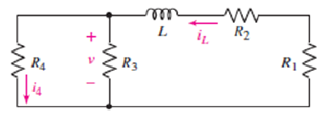
Figure 8.60
Expert Solution & Answer

Trending nowThis is a popular solution!

Students have asked these similar questions
Question 8.
12V
in
R₁
A
R₁
5
V
C
R₂2
w
R₂
4
Consider the circuit below, where the capacitor is uncharged, and the switch is open.
The different elements of the circuit have the following values: R₁ = 22, R₂ = 22, R3 = 422, R₁ = 82, R₁ = 82 and C = 10 µF.
What is the current I₁ in the circuit when the switch is moved to position 1?
Enter your answer, in Amps, in the box below.
The answer is acceptable within a tolerance of 0.1 A.
h₁:
R3
After a long time that the switch has been closed, what is the voltage Vc across the capacitor?
Enter your answer, in Volts, in the box below.
The answer is acceptable within a tolerance of 0.1 V.
Vc:
8.3.1 For the RLC circuit shown in the image below, if R1 = 3 2 and R2 = 7 2, C =
0.44 F, and the power source Vs = 7 V, determine the initial value iL (0* ). Please
pay attention: the numbers may change since they are randomized. Your answer
must include 2 places after the decimal point, and proper SI unit.
R2
+
2u(t) A
R
Vs
Your Answer:
Answer
units
118
ll
8.3.3 For the RLC circuit shown in the image below, if R1 = 7 2 and R2 = 7 2, C =
0.36 F, and the power source Vs = 18 V, determine the initial value VR (0T).
%3D
Please pay attention: the numbers may change since they are randomized. Your
answer must include 2 places after the decimal point, and proper SI unit.
R2
Vc
+
VR
R1
2u(t) A
Vs
Your Answer:
Answer
units
118
ll
Chapter 8 Solutions
Loose Leaf for Engineering Circuit Analysis Format: Loose-leaf
Ch. 8.1 - For the circuit in Fig. 8.2, what value of...Ch. 8.1 - Noting carefully how the circuit changes once the...Ch. 8.2 - In a source-free series RC circuit, find the...Ch. 8.3 - Prob. 4PCh. 8.3 - Prob. 5PCh. 8.4 - Prob. 6PCh. 8.4 - Prob. 7PCh. 8.4 - Prob. 8PCh. 8.5 - Evaluate each of the following at t = 0.8: (a)...Ch. 8.6 - For the circuit of Fig. 8.37, find vc(t) at t...
Ch. 8.7 - Prob. 11PCh. 8.7 - The voltage source 60 40u(t) V is in series with...Ch. 8.7 - Prob. 13PCh. 8.8 - Prob. 14PCh. 8.8 - Prob. 15PCh. 8 - A source-free RC circuit has R = 4 k and C = 22 F,...Ch. 8 - A source-free RC circuit has v(0) = 12 V and R =...Ch. 8 - The resistor in the circuit of Fig. 8.51 has been...Ch. 8 - Prob. 4ECh. 8 - Prob. 5ECh. 8 - Prob. 6ECh. 8 - Prob. 7ECh. 8 - Prob. 8ECh. 8 - Prob. 9ECh. 8 - The switch in Fig. 8.56 has been closed for a long...Ch. 8 - For the circuit in Fig. 8.56, find (a) the total...Ch. 8 - Design a capacitor-based circuit that can achieve...Ch. 8 - (a) Graph the function f (t) = 10e2t over the...Ch. 8 - The current i(t) flowing through a 1 k resistor is...Ch. 8 - Radiocarbon dating has a similar exponential time...Ch. 8 - For the circuit of Fig. 8.4, compute the time...Ch. 8 - Design a circuit which will produce a current of 1...Ch. 8 - Prob. 18ECh. 8 - Prob. 19ECh. 8 - Referring to the circuit shown in Fig. 8.11,...Ch. 8 - Prob. 21ECh. 8 - With the assumption that the switch in the circuit...Ch. 8 - The switch in Fig. 8.57 has been closed since...Ch. 8 - The switch in the circuit of Fig. 8.58 has been...Ch. 8 - Assuming the switch initially has been open for a...Ch. 8 - (a) Obtain an expression for v(t), the voltage...Ch. 8 - For the circuit of Fig. 8.61, determine ix, iL,...Ch. 8 - Prob. 28ECh. 8 - Prob. 29ECh. 8 - Prob. 30ECh. 8 - Prob. 31ECh. 8 - (a) Obtain an expression for vx as labeled in the...Ch. 8 - Prob. 33ECh. 8 - Prob. 34ECh. 8 - Prob. 35ECh. 8 - Prob. 36ECh. 8 - Prob. 37ECh. 8 - The switch in Fig. 8.70 is moved from A to B at t...Ch. 8 - Prob. 39ECh. 8 - Prob. 40ECh. 8 - Evaluate the following functions at t = 1, 0, and...Ch. 8 - Prob. 42ECh. 8 - Prob. 43ECh. 8 - Prob. 44ECh. 8 - You can use MATLAB to represent the unit-step...Ch. 8 - With reference to the circuit depicted in Fig....Ch. 8 - For the circuit given in Fig. 8.75, (a) determine...Ch. 8 - Prob. 48ECh. 8 - Prob. 49ECh. 8 - You build a portable solar charging circuit...Ch. 8 - The switch in the circuit of Fig. 8.78 has been...Ch. 8 - The switch in the circuit of Fig. 8.78 has been...Ch. 8 - Prob. 53ECh. 8 - Prob. 54ECh. 8 - Prob. 55ECh. 8 - For the circuit represented in Fig. 8.82, (a)...Ch. 8 - Prob. 58ECh. 8 - Prob. 59ECh. 8 - For the circuit given in Fig. 8.85, (a) determine...Ch. 8 - The circuit depicted in Fig. 8.86 contains two...Ch. 8 - Prob. 62ECh. 8 - Prob. 63ECh. 8 - A series RL circuit has a voltage that steps from...Ch. 8 - For the two-source circuit of Fig. 8.89, note that...Ch. 8 - (a) Obtain an expression for iL as labeled in Fig....Ch. 8 - Obtain an expression for i(t) as labeled in the...Ch. 8 - Obtain an expression for i1 as indicated in Fig....Ch. 8 - Plot the current i(t) in Fig. 8.93 if (a) R = 10 ;...Ch. 8 - A dc motor can be modeled as a series RL circuit...Ch. 8 - Prob. 71ECh. 8 - Prob. 72ECh. 8 - A series RC sequentially switched circuit has R =...Ch. 8 - Refer to the circuit of Fig. 8.95, which contains...Ch. 8 - In the circuit of Fig. 8.95, a 3 mF capacitor is...Ch. 8 - Prob. 78E
Knowledge Booster


Learn more about
Need a deep-dive on the concept behind this application? Look no further. Learn more about this topic, electrical-engineering and related others by exploring similar questions and additional content below.Similar questions
- EXERCISE 8.7.17 (a) Find Vs in the network in the figure below if V₁ = 4/0° V. 1 Ω -j1 Ω 1Ω 16 + V, ΣΖΩ + Vs -j1 Ω 32Ωarrow_forward8:15 X Activity Gree... Q Activity Greens theorem Write your solution on a clean bond paper, upload a copy of your solution on google classroom. 1. Use Green's Theorem to evaluate JC (5y-9x)dy-(yx-x³)dx where C is shown below (12) (-2-1) (L-1) 2. Calculate-2x²y dx + 2xy² dy, where C is the circle of radius 3 centered on the origin. (use this formula JJC = (Qx-Py) dA where dA = rdrde).arrow_forward1H + e'u(t) + VR(t) 1F Figure 6.a 6. b) Find the Laplace transformation of the signals shown in Figure 6.b. x(t) 1 ↑ x2(t) 1 2 1 t 4 5, Figure 6.b 7. a) Find the transfer function for the system in Figure 7.a. Sketch pole-zero diagram. Is the system stable? 1 s + 3 s + 2 x(t) y(t) s(s + 3) 2 Figure 7.a b) Find f(t) using inverse Laplace transformation. Sketch the ROC. (8s +10)e -S F(s) = ; -2< Re(s) <-1 (s +1)(s +2) 8. a) Draw the f-i analogous electrical network of the mechanical system shown in Figure 8.a. Page 3 of 7 + +. +arrow_forward
- Picture (1) we can see the circuit where L=4mH, C=2uF and Vs is given in picture (2). The question asks the value of İc at t=8ms. Note: The time (t) given in the graph is in mili seconds (ms) TIAarrow_forward8.3 For a Si solar cell, the dark saturation current is 2 μA and the short circuit cur- rent is 150 mA. When it is optically illuminated, the optically generated current is 0.1 mA. Find the corresponding voltage at current of 100 mA. please tell me his problem in detailarrow_forward8.23 At t=0 s, a 100-V source is switched in series with a 1-k resistor and an uncharged 2-µF capacitor. What are (a) the initial capacitor voltage, (b) the initial current, (c) the initial rate of capacitor voltage increase, and (d) the time required for the capacitor voltage to reach its maximum value?arrow_forward
- In the circuit of Fig. 8_1, which of the following statements is true? 1092 www. 7₁₁=0 25 Ω 5V Fig. 8_1 v(t)=-(2.5) e-2125t, DO Time Constant = 2.5 second ⒸIL (0)-4 (A) VL(0) - 10 V Ⓒi(t)-12 e 24, 10 50 92 w iL 40 mHarrow_forwardQ- A series RLC circuit is observed at w₁ = 1 krad/s, we note that source voltage V₁ = 100/0° results in current I₁ = 0.03231° A. If C = 1µF then find the values of R & L.arrow_forwardYou are investigating the electrical testing circuits and find that, in an inductive circuit, the relationship between instantaneous current i (amps) and the time t (secs) is given by: i = 12.5(1-e-t/CR) You have been asked to determine the time taken for the current to rise from 1 to 2 amps given your own R and C values as follows. R= 140 C= 90arrow_forward
- Problem 4: The voltage source has a square wave input (see chapter 13). If the frequency is 220 kHz and the voltage switches to 10 V at t - 0, find: a) The time constant; b) The current I at t = 0.5us; c) The current I at t = 3.5us; d) The current I att = 6.0us; Use Multisim to confirm your results, and give a screenshot. 10v I5 mH llarrow_forwardChapter 8, Problem 8.137 | Your answer is partially correct. Try again. Find Vo in the network in the figure below using Thévenin's theorem. 12/0 v (+-) ji n 310 -j1 N V, 19 Q Vo 2V, (a) Find the real part of Vo. (b) Find the imaginary part of Vo. (a) V -3.653 (b) V -1.007arrow_forward(b) The voltage across a 4 N resistor of an RC circuit in Figure Q8(b) is given by VR (t) = 2e-6tu(t)V. Determine the total energy dissipated by this resistor using Parseval's Theorem. R C Figure Q8(b)arrow_forward
arrow_back_ios
SEE MORE QUESTIONS
arrow_forward_ios
Recommended textbooks for you
 Introductory Circuit Analysis (13th Edition)Electrical EngineeringISBN:9780133923605Author:Robert L. BoylestadPublisher:PEARSON
 Delmar's Standard Textbook Of ElectricityElectrical EngineeringISBN:9781337900348Author:Stephen L. HermanPublisher:Cengage Learning
 Programmable Logic ControllersElectrical EngineeringISBN:9780073373843Author:Frank D. PetruzellaPublisher:McGraw-Hill Education
 Fundamentals of Electric CircuitsElectrical EngineeringISBN:9780078028229Author:Charles K Alexander, Matthew SadikuPublisher:McGraw-Hill Education
 Electric Circuits. (11th Edition)Electrical EngineeringISBN:9780134746968Author:James W. Nilsson, Susan RiedelPublisher:PEARSON
 Engineering ElectromagneticsElectrical EngineeringISBN:9780078028151Author:Hayt, William H. (william Hart), Jr, BUCK, John A.Publisher:Mcgraw-hill Education,
Introductory Circuit Analysis (13th Edition)
Electrical Engineering
ISBN:9780133923605
Author:Robert L. Boylestad
Publisher:PEARSON
Delmar's Standard Textbook Of Electricity
Electrical Engineering
ISBN:9781337900348
Author:Stephen L. Herman
Publisher:Cengage Learning
Programmable Logic Controllers
Electrical Engineering
ISBN:9780073373843
Author:Frank D. Petruzella
Publisher:McGraw-Hill Education
Fundamentals of Electric Circuits
Electrical Engineering
ISBN:9780078028229
Author:Charles K Alexander, Matthew Sadiku
Publisher:McGraw-Hill Education
Electric Circuits. (11th Edition)
Electrical Engineering
ISBN:9780134746968
Author:James W. Nilsson, Susan Riedel
Publisher:PEARSON
Engineering Electromagnetics
Electrical Engineering
ISBN:9780078028151
Author:Hayt, William H. (william Hart), Jr, BUCK, John A.
Publisher:Mcgraw-hill Education,
ENA 9.2(1)(En)(Alex) Sinusoids & Phasors - Explanation with Example 9.1 ,9.2 & PP 9.2; Author: Electrical Engineering Academy;https://www.youtube.com/watch?v=vX_LLNl-ZpU;License: Standard YouTube License, CC-BY
Electrical Engineering: Ch 10 Alternating Voltages & Phasors (8 of 82) What is a Phasor?; Author: Michel van Biezen;https://www.youtube.com/watch?v=2I1tF3ixNg0;License: Standard Youtube License