
Loose Leaf for Engineering Circuit Analysis Format: Loose-leaf
9th Edition
ISBN: 9781259989452
Author: Hayt
Publisher: Mcgraw Hill Publishers
expand_more
expand_more
format_list_bulleted
Concept explainers
Videos
Textbook Question
Chapter 8, Problem 52E
The switch in the circuit of Fig. 8.78 has been open a really, really, incredibly long time, before being closed without further fanfare at t = 0. (a) Evaluate the current labeled ix at t = 70 ms. (b) Verify your answer with an appropriate SPICE simulation.
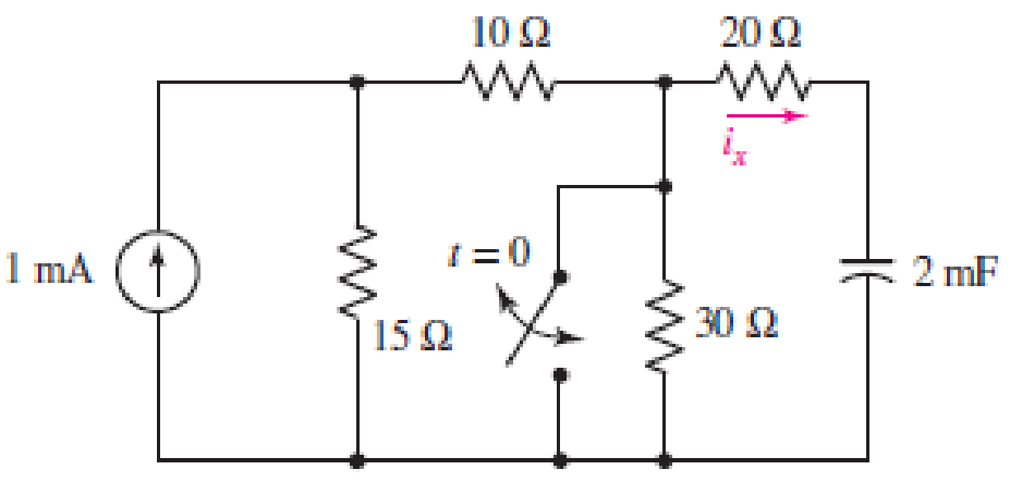
■ FIGURE 8.78
Expert Solution & Answer
Want to see the full answer?
Check out a sample textbook solution
Students have asked these similar questions
Compute the Values: (show solutions)
A
10.0 Ω
5.00 Ω
ww
8.00 Ω
6.00 V
+
+
8.00 Ω 8.00 V
In the circuit above, the ammeter (A) is an ideal ammeter (so without internal resistance); the voltmeter (V) is
also ideal (so with an infinitely large resistance). The two e.m.f. sources have negligible internal resistance.
The voltmeter reads a positive value when the voltage of the +-connector is higher than the voltage of the --
connector (see picture)
The ammeter reads a positive value when the current runs from the +-connector to the --connector.
What are the readings of the ammeter and the voltmeter?
A
10.0 Ω
5.00 Ω
8.00 Ω
+
V
8.00 Ω
6.00 V
+
+
8.00 V
In the circuit above, the ammeter (A) is an ideal ammeter (so without internal resistance); the voltmeter (V) is
also ideal (so with an infinitely large resistance). The two e.m.f. sources have negligible internal resistance.
The voltmeter reads a positive value when the voltage of the +-connector is higher than the voltage of the
connector (see picture)
The ammeter reads a positive value when the current runs from the +-connector to the --connector.
What are the readings of the ammeter and the voltmeter?
Chapter 8 Solutions
Loose Leaf for Engineering Circuit Analysis Format: Loose-leaf
Ch. 8.1 - For the circuit in Fig. 8.2, what value of...Ch. 8.1 - Noting carefully how the circuit changes once the...Ch. 8.2 - In a source-free series RC circuit, find the...Ch. 8.3 - Prob. 4PCh. 8.3 - Prob. 5PCh. 8.4 - Prob. 6PCh. 8.4 - Prob. 7PCh. 8.4 - Prob. 8PCh. 8.5 - Evaluate each of the following at t = 0.8: (a)...Ch. 8.6 - For the circuit of Fig. 8.37, find vc(t) at t...
Ch. 8.7 - Prob. 11PCh. 8.7 - The voltage source 60 40u(t) V is in series with...Ch. 8.7 - Prob. 13PCh. 8.8 - Prob. 14PCh. 8.8 - Prob. 15PCh. 8 - A source-free RC circuit has R = 4 k and C = 22 F,...Ch. 8 - A source-free RC circuit has v(0) = 12 V and R =...Ch. 8 - The resistor in the circuit of Fig. 8.51 has been...Ch. 8 - Prob. 4ECh. 8 - Prob. 5ECh. 8 - Prob. 6ECh. 8 - Prob. 7ECh. 8 - Prob. 8ECh. 8 - Prob. 9ECh. 8 - The switch in Fig. 8.56 has been closed for a long...Ch. 8 - For the circuit in Fig. 8.56, find (a) the total...Ch. 8 - Design a capacitor-based circuit that can achieve...Ch. 8 - (a) Graph the function f (t) = 10e2t over the...Ch. 8 - The current i(t) flowing through a 1 k resistor is...Ch. 8 - Radiocarbon dating has a similar exponential time...Ch. 8 - For the circuit of Fig. 8.4, compute the time...Ch. 8 - Design a circuit which will produce a current of 1...Ch. 8 - Prob. 18ECh. 8 - Prob. 19ECh. 8 - Referring to the circuit shown in Fig. 8.11,...Ch. 8 - Prob. 21ECh. 8 - With the assumption that the switch in the circuit...Ch. 8 - The switch in Fig. 8.57 has been closed since...Ch. 8 - The switch in the circuit of Fig. 8.58 has been...Ch. 8 - Assuming the switch initially has been open for a...Ch. 8 - (a) Obtain an expression for v(t), the voltage...Ch. 8 - For the circuit of Fig. 8.61, determine ix, iL,...Ch. 8 - Prob. 28ECh. 8 - Prob. 29ECh. 8 - Prob. 30ECh. 8 - Prob. 31ECh. 8 - (a) Obtain an expression for vx as labeled in the...Ch. 8 - Prob. 33ECh. 8 - Prob. 34ECh. 8 - Prob. 35ECh. 8 - Prob. 36ECh. 8 - Prob. 37ECh. 8 - The switch in Fig. 8.70 is moved from A to B at t...Ch. 8 - Prob. 39ECh. 8 - Prob. 40ECh. 8 - Evaluate the following functions at t = 1, 0, and...Ch. 8 - Prob. 42ECh. 8 - Prob. 43ECh. 8 - Prob. 44ECh. 8 - You can use MATLAB to represent the unit-step...Ch. 8 - With reference to the circuit depicted in Fig....Ch. 8 - For the circuit given in Fig. 8.75, (a) determine...Ch. 8 - Prob. 48ECh. 8 - Prob. 49ECh. 8 - You build a portable solar charging circuit...Ch. 8 - The switch in the circuit of Fig. 8.78 has been...Ch. 8 - The switch in the circuit of Fig. 8.78 has been...Ch. 8 - Prob. 53ECh. 8 - Prob. 54ECh. 8 - Prob. 55ECh. 8 - For the circuit represented in Fig. 8.82, (a)...Ch. 8 - Prob. 58ECh. 8 - Prob. 59ECh. 8 - For the circuit given in Fig. 8.85, (a) determine...Ch. 8 - The circuit depicted in Fig. 8.86 contains two...Ch. 8 - Prob. 62ECh. 8 - Prob. 63ECh. 8 - A series RL circuit has a voltage that steps from...Ch. 8 - For the two-source circuit of Fig. 8.89, note that...Ch. 8 - (a) Obtain an expression for iL as labeled in Fig....Ch. 8 - Obtain an expression for i(t) as labeled in the...Ch. 8 - Obtain an expression for i1 as indicated in Fig....Ch. 8 - Plot the current i(t) in Fig. 8.93 if (a) R = 10 ;...Ch. 8 - A dc motor can be modeled as a series RL circuit...Ch. 8 - Prob. 71ECh. 8 - Prob. 72ECh. 8 - A series RC sequentially switched circuit has R =...Ch. 8 - Refer to the circuit of Fig. 8.95, which contains...Ch. 8 - In the circuit of Fig. 8.95, a 3 mF capacitor is...Ch. 8 - Prob. 78E
Additional Engineering Textbook Solutions
Find more solutions based on key concepts
Find I0 and I1 in the circuit in Fig.P2.12.
Basic Engineering Circuit Analysis
A constant voltage of 10V is applied to a 50H inductance, as shown in Figure P3.51 Figure P3 51 The current in ...
Electrical Engineering: Principles & Applications (7th Edition)
Write the nodal equations for the network of Fig. 8.137 using the general approach. Find the nodal voltages usi...
Introductory Circuit Analysis (13th Edition)
Three point charges of equal magnitude q, that will yield a zero net electric field at the origin.
Engineering Electromagnetics
Electric power systems provide energy in a variety of commercial and industrial settings. Make a list of system...
Principles and Applications of Electrical Engineering
How many coulombs do 93.8 1016 electrons represent?
Principles Of Electric Circuits
Knowledge Booster


Learn more about
Need a deep-dive on the concept behind this application? Look no further. Learn more about this topic, electrical-engineering and related others by exploring similar questions and additional content below.Similar questions
- A circuit comprises an inductor of 9 H of negligible resistance connected in series with a 60 Ω resistor and a 240 V dc source. Determine the following: (a) The time constant in seconds. (b) The current after 1 time constant. (c) Time to develop maximum current in seconds.arrow_forwardQ8. Assume the switch has been opened for a long time. The switch is closed at t = 0 s. (a) Find the equation of vo(t) for t > 0 s. (b) Plot vo(t) as a function of time starting from t < 0 s. 13 V 6Ω www t = 0 to 3Ω 4 V 5Ω M 4 mF + vo(t)arrow_forwardShown below is a typical setup for a solar battery system. Sun’s energy is converted to electricity using solar PV modules. To match the output voltage of the PV module to the battery's, a charge controller is used which is a DC-DC converter. The sun’s output power is given as 1000 W/m2. The solar module has a surface area of 1 m^2 with a conversion efficiency of 10%. A charge controller converts the 20V module voltage to 12V battery voltage, with an efficiency of 84% The battery is 12V with a capacity of 10Ah. Assuming the battery is half empty (or half full, depending on your personality) and the bulb is powered on, how long will it take for the battery to be fully charged? How long can the bulb be powered at night, assuming full battery when the sun goes down and that you can fully drain the battery? (answer in hours)arrow_forward
- (a) Construct circuits that produce the following outputs.i. (x + y + z)(x1 y1 z1 )ii. x1(y1+z1)1(b) A committee of three individuals decides issues for an organization.Each individual votes either yes or no for each proposal that arises.A proposal is passed if it received at least two yes votes. Design a circuit that determines whether a proposal passes. (c) i. Translate ∀x[C(x) ∨ ∃y(C(y) ∧ F(x, y)] into English, where C(x): x has a computerF(x, y): x and y are friendsThe domain for both x and y is all students in your school. ii. Translate ∃x∀y∀z[(F(x, y)∧F(x, z)∧(y not the some as z)) −→ ¬F(y, z)] where; F(a, b):a and b are friends. The domain of x, y and z consists of all students in your schoolarrow_forwardPart A: Open circuit and short circuit faults are important in circuit analysis. These are the most common faults for any circuit. Discuss open circuit and short circuit fault in a circuit. Then discuss why do you think capacitor acts as an open circuit, but inductor acts as a short circuit for a DC input. A detail response is required. Part B: Calculate the time constant and voltage v(t) at t=0, 100s, 200s, 500s, 800s for the following circuitarrow_forwardFor the circuit in Figure 3 the switch is in the left position for several minutes: (a) Find the Initlal voltage, o on the capacitor just before the switch is flipped (b) Find an expression v(t) that describes the voltage across the 20 N resistor after the switch has been Figure 3 1Ω 60 N flipped to the right NOTE: Remember what we said in class: use a Circuit-Specific Equation to get a value you know. Then solve for whatever else the problem asks for O 12 V 5 2 -50 μF 80 Ω 20Ωarrow_forward
- A 42 µF capacitor is in parallel with a 230 Ko resistor and a 300 V power supply. The switch is closed and opened. If the digital multi-meter (DMM) has an internal resistance that is equal to resistor resistance, How long does it take for the voltage shown by the DMM to drop to 100 V? Marrow_forwardTwo resistors and a capacitor are connected in a network with a switch S. The switch S has been open for a long time and closes at t=0; a) Calculate U just after t=0 b) Calculate U after a long time After being switched on for a long time, the circuit breaker S opens (breaks). c) Calculate the current I2 through the resistor R2 immediately after breaking d) Calculate I2 long time after the breakarrow_forward8. The PMOS in the image below, is specified to have Vth = -1V and kp = 0.4/V 2. The ideal current source has 1 = 0.2mA. Find the voltage Vx. 10V 5ΚΩ ↓arrow_forward
- The following circuit is given. Here, E = 1 V, C = 20 mF, and R = 20 Q. The switch is closed at instant t = 0 s. Compute the voltage v, after an interval of time of 10T, being T the time constant of the circuit (result in volt). OE ER R t = 0 sarrow_forward9. In Figure 8, the switch S has been closed for a long time and the circuit carries a constant current. 30 V S 6kn W W 3ΚΩ 500 Ω W 12μF Figure 8. (a) What is the voltage across the capacitor? Show your work or explain. (b) Now the switch S is opened at t = 0. (Switch S is open for all questions below) (i) What is the initial discharge current through the 50052 resistor? (ii) How long does it take the capacitor to discharge to one-fifth of its original voltage? (iii) Determine the charge on the capacitor at time t = 0.05 s. (iv) What is the amount of charge left on the capacitor after 75 time constants has passed (t = 75RC).arrow_forwardThe switch in the circuit shown has been in position a for a longtime. At t=0, it moves to position b. Find vC(t) for t≥0 2. 8.8 Find i(t) for t≥0 for the circuit Repeat if the 80 Ω resistor isreplaced by a 100 Ω resistorarrow_forward
arrow_back_ios
SEE MORE QUESTIONS
arrow_forward_ios
Recommended textbooks for you
 Introductory Circuit Analysis (13th Edition)Electrical EngineeringISBN:9780133923605Author:Robert L. BoylestadPublisher:PEARSON
 Delmar's Standard Textbook Of ElectricityElectrical EngineeringISBN:9781337900348Author:Stephen L. HermanPublisher:Cengage Learning
 Programmable Logic ControllersElectrical EngineeringISBN:9780073373843Author:Frank D. PetruzellaPublisher:McGraw-Hill Education
 Fundamentals of Electric CircuitsElectrical EngineeringISBN:9780078028229Author:Charles K Alexander, Matthew SadikuPublisher:McGraw-Hill Education
 Electric Circuits. (11th Edition)Electrical EngineeringISBN:9780134746968Author:James W. Nilsson, Susan RiedelPublisher:PEARSON
 Engineering ElectromagneticsElectrical EngineeringISBN:9780078028151Author:Hayt, William H. (william Hart), Jr, BUCK, John A.Publisher:Mcgraw-hill Education,
Introductory Circuit Analysis (13th Edition)
Electrical Engineering
ISBN:9780133923605
Author:Robert L. Boylestad
Publisher:PEARSON
Delmar's Standard Textbook Of Electricity
Electrical Engineering
ISBN:9781337900348
Author:Stephen L. Herman
Publisher:Cengage Learning
Programmable Logic Controllers
Electrical Engineering
ISBN:9780073373843
Author:Frank D. Petruzella
Publisher:McGraw-Hill Education
Fundamentals of Electric Circuits
Electrical Engineering
ISBN:9780078028229
Author:Charles K Alexander, Matthew Sadiku
Publisher:McGraw-Hill Education
Electric Circuits. (11th Edition)
Electrical Engineering
ISBN:9780134746968
Author:James W. Nilsson, Susan Riedel
Publisher:PEARSON
Engineering Electromagnetics
Electrical Engineering
ISBN:9780078028151
Author:Hayt, William H. (william Hart), Jr, BUCK, John A.
Publisher:Mcgraw-hill Education,
ENA 9.2(1)(En)(Alex) Sinusoids & Phasors - Explanation with Example 9.1 ,9.2 & PP 9.2; Author: Electrical Engineering Academy;https://www.youtube.com/watch?v=vX_LLNl-ZpU;License: Standard YouTube License, CC-BY
Electrical Engineering: Ch 10 Alternating Voltages & Phasors (8 of 82) What is a Phasor?; Author: Michel van Biezen;https://www.youtube.com/watch?v=2I1tF3ixNg0;License: Standard Youtube License