
Loose Leaf for Engineering Circuit Analysis Format: Loose-leaf
9th Edition
ISBN: 9781259989452
Author: Hayt
Publisher: Mcgraw Hill Publishers
expand_more
expand_more
format_list_bulleted
Concept explainers
Videos
Textbook Question
Chapter 8.1, Problem 2P
Noting carefully how the circuit changes once the switch in the circuit of Fig. 8.5 is thrown, determine v(t) at t = 0 and at t = 160 μs.
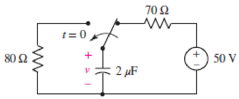
■ FIGURE 8.5
Expert Solution & Answer
Want to see the full answer?
Check out a sample textbook solution
Students have asked these similar questions
8.3.1 For the RLC circuit shown in the image below, if R1 = 3 2 and R2 = 7 2, C =
0.44 F, and the power source Vs = 7 V, determine the initial value iL (0* ). Please
pay attention: the numbers may change since they are randomized. Your answer
must include 2 places after the decimal point, and proper SI unit.
R2
+
2u(t) A
R
Vs
Your Answer:
Answer
units
118
ll
8.5 From the circuit in the figure, if the switch was initially connected with a resistance of 2Ω for a long time and opened as shown at time t = 0, find i0(t) and v0(t) when t > 0
Question 8.
12V
in
R₁
A
R₁
5
V
C
R₂2
w
R₂
4
Consider the circuit below, where the capacitor is uncharged, and the switch is open.
The different elements of the circuit have the following values: R₁ = 22, R₂ = 22, R3 = 422, R₁ = 82, R₁ = 82 and C = 10 µF.
What is the current I₁ in the circuit when the switch is moved to position 1?
Enter your answer, in Amps, in the box below.
The answer is acceptable within a tolerance of 0.1 A.
h₁:
R3
After a long time that the switch has been closed, what is the voltage Vc across the capacitor?
Enter your answer, in Volts, in the box below.
The answer is acceptable within a tolerance of 0.1 V.
Vc:
Chapter 8 Solutions
Loose Leaf for Engineering Circuit Analysis Format: Loose-leaf
Ch. 8.1 - For the circuit in Fig. 8.2, what value of...Ch. 8.1 - Noting carefully how the circuit changes once the...Ch. 8.2 - In a source-free series RC circuit, find the...Ch. 8.3 - Prob. 4PCh. 8.3 - Prob. 5PCh. 8.4 - Prob. 6PCh. 8.4 - Prob. 7PCh. 8.4 - Prob. 8PCh. 8.5 - Evaluate each of the following at t = 0.8: (a)...Ch. 8.6 - For the circuit of Fig. 8.37, find vc(t) at t...
Ch. 8.7 - Prob. 11PCh. 8.7 - The voltage source 60 40u(t) V is in series with...Ch. 8.7 - Prob. 13PCh. 8.8 - Prob. 14PCh. 8.8 - Prob. 15PCh. 8 - A source-free RC circuit has R = 4 k and C = 22 F,...Ch. 8 - A source-free RC circuit has v(0) = 12 V and R =...Ch. 8 - The resistor in the circuit of Fig. 8.51 has been...Ch. 8 - Prob. 4ECh. 8 - Prob. 5ECh. 8 - Prob. 6ECh. 8 - Prob. 7ECh. 8 - Prob. 8ECh. 8 - Prob. 9ECh. 8 - The switch in Fig. 8.56 has been closed for a long...Ch. 8 - For the circuit in Fig. 8.56, find (a) the total...Ch. 8 - Design a capacitor-based circuit that can achieve...Ch. 8 - (a) Graph the function f (t) = 10e2t over the...Ch. 8 - The current i(t) flowing through a 1 k resistor is...Ch. 8 - Radiocarbon dating has a similar exponential time...Ch. 8 - For the circuit of Fig. 8.4, compute the time...Ch. 8 - Design a circuit which will produce a current of 1...Ch. 8 - Prob. 18ECh. 8 - Prob. 19ECh. 8 - Referring to the circuit shown in Fig. 8.11,...Ch. 8 - Prob. 21ECh. 8 - With the assumption that the switch in the circuit...Ch. 8 - The switch in Fig. 8.57 has been closed since...Ch. 8 - The switch in the circuit of Fig. 8.58 has been...Ch. 8 - Assuming the switch initially has been open for a...Ch. 8 - (a) Obtain an expression for v(t), the voltage...Ch. 8 - For the circuit of Fig. 8.61, determine ix, iL,...Ch. 8 - Prob. 28ECh. 8 - Prob. 29ECh. 8 - Prob. 30ECh. 8 - Prob. 31ECh. 8 - (a) Obtain an expression for vx as labeled in the...Ch. 8 - Prob. 33ECh. 8 - Prob. 34ECh. 8 - Prob. 35ECh. 8 - Prob. 36ECh. 8 - Prob. 37ECh. 8 - The switch in Fig. 8.70 is moved from A to B at t...Ch. 8 - Prob. 39ECh. 8 - Prob. 40ECh. 8 - Evaluate the following functions at t = 1, 0, and...Ch. 8 - Prob. 42ECh. 8 - Prob. 43ECh. 8 - Prob. 44ECh. 8 - You can use MATLAB to represent the unit-step...Ch. 8 - With reference to the circuit depicted in Fig....Ch. 8 - For the circuit given in Fig. 8.75, (a) determine...Ch. 8 - Prob. 48ECh. 8 - Prob. 49ECh. 8 - You build a portable solar charging circuit...Ch. 8 - The switch in the circuit of Fig. 8.78 has been...Ch. 8 - The switch in the circuit of Fig. 8.78 has been...Ch. 8 - Prob. 53ECh. 8 - Prob. 54ECh. 8 - Prob. 55ECh. 8 - For the circuit represented in Fig. 8.82, (a)...Ch. 8 - Prob. 58ECh. 8 - Prob. 59ECh. 8 - For the circuit given in Fig. 8.85, (a) determine...Ch. 8 - The circuit depicted in Fig. 8.86 contains two...Ch. 8 - Prob. 62ECh. 8 - Prob. 63ECh. 8 - A series RL circuit has a voltage that steps from...Ch. 8 - For the two-source circuit of Fig. 8.89, note that...Ch. 8 - (a) Obtain an expression for iL as labeled in Fig....Ch. 8 - Obtain an expression for i(t) as labeled in the...Ch. 8 - Obtain an expression for i1 as indicated in Fig....Ch. 8 - Plot the current i(t) in Fig. 8.93 if (a) R = 10 ;...Ch. 8 - A dc motor can be modeled as a series RL circuit...Ch. 8 - Prob. 71ECh. 8 - Prob. 72ECh. 8 - A series RC sequentially switched circuit has R =...Ch. 8 - Refer to the circuit of Fig. 8.95, which contains...Ch. 8 - In the circuit of Fig. 8.95, a 3 mF capacitor is...Ch. 8 - Prob. 78E
Knowledge Booster


Learn more about
Need a deep-dive on the concept behind this application? Look no further. Learn more about this topic, electrical-engineering and related others by exploring similar questions and additional content below.Similar questions
- 8.3.3 For the RLC circuit shown in the image below, if R1 = 7 2 and R2 = 7 2, C = 0.36 F, and the power source Vs = 18 V, determine the initial value VR (0T). %3D Please pay attention: the numbers may change since they are randomized. Your answer must include 2 places after the decimal point, and proper SI unit. R2 Vc + VR R1 2u(t) A Vs Your Answer: Answer units 118 llarrow_forward3. The switch in the following circuit has been in position a for a long time and instantaneously moves to position b at t = 0. a. Determine the current, i (t), with the switch in position a (i.e. for t = 0-). b. Determine i (t) just after the switch moves to b and after a long time (i.e. t= 0* and t = ). c. Determine the time constant, t, for the switch in position b. d. Write out the equation for the i (t), for t> 0. e. Plot the current i (t) for t> 0. a 4kQ 2500 5kn t = 0 12V 15ka 20V | 340mHarrow_forwardR₁ w £₁10 V R₂10 R₁ ww 40 HI R. SA FIG. 8.121 Rs www 30 E₂2=6Varrow_forward
- • AUIB + 14 Arial نص عادي 100% ... 31 11· 2I 3 I4I5 6.I 7.I8 I9 110:I 11 I 12 I 13 I 14 I 15 1 The circuit in Fig. 8.12 has reached steady state at t = 0. If the make- before-break switch moves to position b at t = 0, calculate i(f) for t> 0. 17 1 18 F 10 Ω a ww t=0 50 V 52 1H Figure 8.12 For Practice Prob. 8.4. Answer: e'(5 cos 1.6583t – 7.5378 sin 1.6583f) A. AR 02:22 acer ASPIRE ONE F1 F2 F3 F4 F5 F6 F7 z' F8 F9 F10 F11 F12 PrtSc Pause Break NumLk Scr Lk SysRq $ & 7 8 8. 5 O 6 9 ww %23 12 1 11: 10. 8 6arrow_forward1H + e'u(t) + VR(t) 1F Figure 6.a 6. b) Find the Laplace transformation of the signals shown in Figure 6.b. x(t) 1 ↑ x2(t) 1 2 1 t 4 5, Figure 6.b 7. a) Find the transfer function for the system in Figure 7.a. Sketch pole-zero diagram. Is the system stable? 1 s + 3 s + 2 x(t) y(t) s(s + 3) 2 Figure 7.a b) Find f(t) using inverse Laplace transformation. Sketch the ROC. (8s +10)e -S F(s) = ; -2< Re(s) <-1 (s +1)(s +2) 8. a) Draw the f-i analogous electrical network of the mechanical system shown in Figure 8.a. Page 3 of 7 + +. +arrow_forward9. In Figure 8, the switch S has been closed for a long time and the circuit carries a constant current. 30 V S 6kn W W 3ΚΩ 500 Ω W 12μF Figure 8. (a) What is the voltage across the capacitor? Show your work or explain. (b) Now the switch S is opened at t = 0. (Switch S is open for all questions below) (i) What is the initial discharge current through the 50052 resistor? (ii) How long does it take the capacitor to discharge to one-fifth of its original voltage? (iii) Determine the charge on the capacitor at time t = 0.05 s. (iv) What is the amount of charge left on the capacitor after 75 time constants has passed (t = 75RC).arrow_forward
- The electricity supplied by a typical wall socket is driven by an alternating current. This alternating current gives rise to a voltage that oscillates (peak-to-peak) 60 times each second and ranges from −120V to +120V . Find a function, V (t), which models the voltage as a function of time and fix any constants involved based on the information given. (You may choose the value of V (t) at t = 0.)arrow_forward8002 80V t=0 3F 0.5i(t) 30Ω www 5002 vi(t) The switch in the circuit has been closed for a long time. At t=0 the switch opens. a) Determine the voltage across the capacitor at t-0 b) For t>0, determine the resistance seen at the terminals of the capacitor and the time constant of the circuit. c) Determine i(t) for t>0.arrow_forward8.4 Step-Response Series RLC Circuits (3) Example 4 Having been in position for a long time, the switch in the circuit below is moved to position b at t = 0. Find v(t) and vR(t) for t > 0. 2.5 H 10Ω a ww- 12 V 22 10 V • Please refer to lecture or textbook for more detail elaboration. Answer: v(t) = {10 + [(-2cos3.464t – 1.1547sin3.464t)e-2t]} V VR(t)= [2.31sin3.464t]e-2t V 15 -19 wwarrow_forward
- The switch in the circuit shown has been in position a for a longtime. At t=0, it moves to position b. Find vC(t) for t≥0 2. 8.8 Find i(t) for t≥0 for the circuit Repeat if the 80 Ω resistor isreplaced by a 100 Ω resistorarrow_forwardThe switch in the circuit in Fig. below has been open for a long time. At t=0 the switch is closed. The capacitor voltage (V. (t = 0) )is: 1.8 kN 1 =0 120 V 10 µF 12 kN { 68 k2arrow_forwardQ8. Assume the switch has been opened for a long time. The switch is closed at t = 0 s. (a) Find the equation of vo(t) for t > 0 s. (b) Plot vo(t) as a function of time starting from t < 0 s. 13 V 6Ω www t = 0 to 3Ω 4 V 5Ω M 4 mF + vo(t)arrow_forward
arrow_back_ios
SEE MORE QUESTIONS
arrow_forward_ios
Recommended textbooks for you
 Introductory Circuit Analysis (13th Edition)Electrical EngineeringISBN:9780133923605Author:Robert L. BoylestadPublisher:PEARSON
 Delmar's Standard Textbook Of ElectricityElectrical EngineeringISBN:9781337900348Author:Stephen L. HermanPublisher:Cengage Learning
 Programmable Logic ControllersElectrical EngineeringISBN:9780073373843Author:Frank D. PetruzellaPublisher:McGraw-Hill Education
 Fundamentals of Electric CircuitsElectrical EngineeringISBN:9780078028229Author:Charles K Alexander, Matthew SadikuPublisher:McGraw-Hill Education
 Electric Circuits. (11th Edition)Electrical EngineeringISBN:9780134746968Author:James W. Nilsson, Susan RiedelPublisher:PEARSON
 Engineering ElectromagneticsElectrical EngineeringISBN:9780078028151Author:Hayt, William H. (william Hart), Jr, BUCK, John A.Publisher:Mcgraw-hill Education,
Introductory Circuit Analysis (13th Edition)
Electrical Engineering
ISBN:9780133923605
Author:Robert L. Boylestad
Publisher:PEARSON
Delmar's Standard Textbook Of Electricity
Electrical Engineering
ISBN:9781337900348
Author:Stephen L. Herman
Publisher:Cengage Learning
Programmable Logic Controllers
Electrical Engineering
ISBN:9780073373843
Author:Frank D. Petruzella
Publisher:McGraw-Hill Education
Fundamentals of Electric Circuits
Electrical Engineering
ISBN:9780078028229
Author:Charles K Alexander, Matthew Sadiku
Publisher:McGraw-Hill Education
Electric Circuits. (11th Edition)
Electrical Engineering
ISBN:9780134746968
Author:James W. Nilsson, Susan Riedel
Publisher:PEARSON
Engineering Electromagnetics
Electrical Engineering
ISBN:9780078028151
Author:Hayt, William H. (william Hart), Jr, BUCK, John A.
Publisher:Mcgraw-hill Education,
ENA 9.2(1)(En)(Alex) Sinusoids & Phasors - Explanation with Example 9.1 ,9.2 & PP 9.2; Author: Electrical Engineering Academy;https://www.youtube.com/watch?v=vX_LLNl-ZpU;License: Standard YouTube License, CC-BY
Electrical Engineering: Ch 10 Alternating Voltages & Phasors (8 of 82) What is a Phasor?; Author: Michel van Biezen;https://www.youtube.com/watch?v=2I1tF3ixNg0;License: Standard Youtube License