
System Dynamics
3rd Edition
ISBN: 9780073398068
Author: III William J. Palm
Publisher: MCG
expand_more
expand_more
format_list_bulleted
Videos
Textbook Question
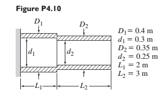
Chapter 4, Problem 4.10P
Compute the equivalent torsional spring constant of the stepped shaft arrangement shown in Figure P4.10. For the shaft material,
Expert Solution & Answer
Want to see the full answer?
Check out a sample textbook solution
Students have asked these similar questions
The idler pulley mechanism shown in Figure P4.12 mustsupport belt tensions of P = l30 lb. Rigid bar ABC is supported byrod (1), which has a diameter of 0.188 in. and a yield strength of35,000 psi. Rod (1) is connected at A and B with 0.25 in. diameterpins in double-shear connections. A 0.25 in. diameter pin in a singleshearconnection holds rigid bar ABC at support C. Each pin has anultimate shear strength of 42,000 psi. Overall dimensions of themechanism are a = 12 in., b = 9 in., c = 7 in., and d = 3 in. Determine(a) the factor of safety for rod (1) with respect to its yield strength.(b) the factor of safety for pin B with respect to its ultimate shearstrength.(c) the factor of safety for pin C with respect to its ultimate shearstrength.
Figure below shows a body of mass m attached to a spring of stiffness k. Find the differential equation for the displacement, x
The mechanism shown in Figure P6.10 is in equilibriumfor an applied load P = 20 kN. Specifications for the mechanismlimit the shear stress in the steel [G = 80 GPa] shaft BC to 70 MPa,the shear stress in bolt A to 100 MPa, and the vertical deflection ofjoint D to a maximum value of 25 mm. Assume that the bearingsallow the shaft to rotate freely. Using L = 1,200 mm, a = 110 mm,and b = 210 mm, calculate(a) the minimum diameter required for shaft BC.(b) the minimum diameter required for bolt A.
Chapter 4 Solutions
System Dynamics
Ch. 4 - Prob. 4.1PCh. 4 - In the spring arrangement shown in Figure P4.2....Ch. 4 - In the arrangement shown in Figure P4.3, a cable...Ch. 4 - In the spring arrangement shown in Figure P4.4,...Ch. 4 - For the system shown in Figure P4.5, assume that...Ch. 4 - The two stepped solid cylinders in Figure P4.6...Ch. 4 - A table with four identical legs supports a...Ch. 4 - The beam shown in Figure P4.8 has been stiffened...Ch. 4 - Determine the equivalent spring constant of the...Ch. 4 - Compute the equivalent torsional spring constant...
Ch. 4 - Plot the spring force felt by the mass shown in...Ch. 4 - Calculate the expression for the natural frequency...Ch. 4 - Prob. 4.13PCh. 4 - Obtain the expression for the natural frequency of...Ch. 4 - 4.15 A connecting rod having a mass of 3.6 kg is...Ch. 4 - Calculate the expression for the natural frequency...Ch. 4 - For each of the systems shown in Figure P4.17, the...Ch. 4 - The mass m in Figure P4.18 is attached to a rigid...Ch. 4 - In the pulley system shown in Figure P4.19, the...Ch. 4 - Prob. 4.20PCh. 4 - Prob. 4.21PCh. 4 - Prob. 4.22PCh. 4 - In Figure P4.23, assume that the cylinder rolls...Ch. 4 - In Figure P4.24 when x1=x2=0 the springs are at...Ch. 4 - 4.25 In Figure P4.25 model the three shafts as...Ch. 4 - In Figure P4.26 when 1=2=0 the spring is at its...Ch. 4 - Prob. 4.27PCh. 4 - For the system shown in Figure P4.28, suppose that...Ch. 4 - For the system shown in Figure P4.29, suppose that...Ch. 4 - Prob. 4.30PCh. 4 - For Figure P4.31, the equilibrium position...Ch. 4 - Prob. 4.32PCh. 4 - Prob. 4.33PCh. 4 - 4.34 For Figure P4.34, assume that the cylinder...Ch. 4 - Use the Rayleigh method to obtain an expression...Ch. 4 - Prob. 4.36PCh. 4 - 4.37 Determine the natural frequency of the system...Ch. 4 - Determine the natural frequency of the system...Ch. 4 - Use Rayleigh's method to calculate the expression...Ch. 4 - Prob. 4.40PCh. 4 - Prob. 4.41PCh. 4 - Prob. 4.42PCh. 4 - The vibration of a motor mounted on the end of a...Ch. 4 - Prob. 4.44PCh. 4 - Prob. 4.45PCh. 4 - A certain cantilever beam vibrates at a frequency...Ch. 4 - Prob. 4.47PCh. 4 - 4.48 The static deflection of a cantilever beam is...Ch. 4 - Figure P4.49 shows a winch supported by a...Ch. 4 - Prob. 4.50PCh. 4 - Prob. 4.51PCh. 4 - Prob. 4.52PCh. 4 - 4.53 In Figure P4.53 a motor supplies a torque T...Ch. 4 - Derive the equation of motion for the lever system...Ch. 4 - Prob. 4.55PCh. 4 - Figure P4.56a shows a Houdaille damper, which is a...Ch. 4 - 4.57 Refer to Figure P4.57. Determine the...Ch. 4 - For the system shown in Figure P4.58, obtain the...Ch. 4 - Find the transfer function ZsXs for the system...Ch. 4 - Prob. 4.60PCh. 4 - Find the transfer function YsXs for the system...Ch. 4 - Prob. 4.62PCh. 4 - 4.63 In the system shown in Figure P4.63, the...Ch. 4 - Prob. 4.64PCh. 4 - Figure P4.65 shows a rack-and-pinion gear in which...Ch. 4 - Figure P4.66 shows a drive train with a spur-gear...Ch. 4 - Prob. 4.67PCh. 4 - Prob. 4.68PCh. 4 - Prob. 4.69PCh. 4 - Figure P4.70 shows a quarter-car model that...Ch. 4 - Prob. 4.71PCh. 4 - 4.72 Derive the equation of motion for the system...Ch. 4 - A boxcar moving at 1.3 m/s hits the shock absorber...Ch. 4 - For the systems shown in Figure P4.74, assume that...Ch. 4 - Refer to Figure P4.75a, which shows a ship’s...Ch. 4 - In this problem, we make all the same assumptions...Ch. 4 - Refer to Figure P4.79a, which shows a water tank...Ch. 4 - The “sky crane” shown on the text cover was a...Ch. 4 - Prob. 4.81PCh. 4 - Prob. 4.82PCh. 4 - Suppose a mass in moving with a speed 1 becomes...Ch. 4 - Consider the system shown in Figure 4.6.3. Suppose...Ch. 4 - Prob. 4.86PCh. 4 - Figure P4.87 shows a mass m with an attached...Ch. 4 - Figure P4.88 represents a drop forging process....Ch. 4 - Refer to Figure P4.89. A mass m drops from a...Ch. 4 - Prob. 4.90PCh. 4 - (a) Obtain the equations of motion of the system...Ch. 4 - Refer to part (a) of Problem 4.90. Use MATLAB to...Ch. 4 - Refer to Problem 4.91. Use MATLAB to obtain the...Ch. 4 - 4.94 (a) Obtain the equations of motion of the...Ch. 4 -
4.95 (a) Obtain the equations of motion of the...
Knowledge Booster


Learn more about
Need a deep-dive on the concept behind this application? Look no further. Learn more about this topic, mechanical-engineering and related others by exploring similar questions and additional content below.Similar questions
- Find the equivalent spring constant spring constant of the system. Say, k1 = 20 lb/in, k2 = 35 lb/in, k3=18 lb/in,k4 = 50 lb/in, k5 = 45 lb/inarrow_forwardQ4/ For the figure below the spring is used to stop a 10 kg package. If the maximum deflection in the spring is 70 mm, (a) the total work of the system in the figure below is: 8m/s H=0,25 /K=400N/m 10kg 500m 0-30 (b): The total work when theta =0 equal to: *arrow_forwardIn the mechanical system in the figure, a rigid rod is bedded at point P and has mass m at its end. can rotate vertically. At the other end of the rod, a spring (k) and a damper (c) are attached. Draw the Free-Body Diagram of the system, obtain the Equation of Motion (the vertical position of the ball We assume that the displacement x is very small and the bar is massless).arrow_forward
- 3. Consider the spring-mass system in an elevator that moves vertically. The natural length of the spring is as shown in the figure below, and at time t=0 the elevator starts moving with prescribed displacement y(t). Suppose that the relative displacement of the mass is x(t), i.e., its displacement with respect to the elevator. Assume mass m can only move vertically, the elevator is massless, and gravity is included. a. Derive the equation of motion of the mass using Newton's 2nd law. b. When is the mass in the elevator in a condition of effective "zero gravity"? y(t) x(t)arrow_forwardFind the global stiffness matrix, displacement at node 1&2, reaction forces at 1&4, and force in spring for the following figure shown below. k1=90 N/mm, k2=1800 N/mm, k3=80 N/mm, P=600 N and u1=u4=0arrow_forward1. A beam with the triangular cross section of Figure P4.7 is of length L and madeof material with Young’s modulus E. It is built in at one end and loaded by a force Fin the x-direction at the other end. Find the two components of displacement at theloaded end.arrow_forward
- Figure 1.29 shows the suspension system of a freight truck with a parallel-spring arrangement. Find the equivalent spring constant of the suspension if each of the three helical springs is made of steel with a shear modulus G = 100 GPaand has 10 effective turns, mean coil diameter D = 50 cm, and wire diameter d = 5 cmarrow_forwardFor the simple pendulum shown in the figure, write the governing equation in s-domain. Assume small angles and linearize your model. Initial conditions are zero. Explain each step clearly. - 0(1) L, length m, massarrow_forwardRefer to Figure Q2. A tray of mass mı is supported by 3 springs as shown in Figure 3(a). The natural frequency fa is 5.0Hz. An additional mass motor of m2 = 3.0kg (in OFF condition) is placed at the center on top of the mass, the natural frequency is observed to be 2.5Hz. a) Calculate the mass mı. The motor m2 is ON and it rotates at the speed of 600 rpm. Calculate: a) The transmissibility b) Attenuation c) Explain what will happen if the system run at Resonant Frequency m2 m1 Figure 2(a): Original system Figure 2(b): system with m2 addedarrow_forward
- Consider three masses m1, m2, and m3 connected by two springs as in the figure below. Suppose m1 = 3 = m3 and m2 = 2 and k12 = 12 = k23. Use a second-order system to find the general solution.arrow_forward3. Imagine a door which can swings into and out of a room. The door has a closer with a spring stiffness of 71 N-m/rad and damping of 7.5 N-m-s/rad and mass moment of inertia of the door with respect to the hinge is 20 kg-m?. If the door is held open and then let go from an angle of 50 degrees, how long will the door continue to swing into and out of the room? How many times will it swings before it will closed? Assume that the door is considered closed when the amplitude has decreased to 2.5 degrees. Assume that small angle approximation holds, such that sin(theta) = theta. %3Darrow_forward4 = k = k k2 = 2k F X kz = 3k 1. Derive the expression for the equivalent spring constant that relates the applied force F to the resulting displacement x of the system shown in the figure above. Assume the displacement of the link to be small.arrow_forward
arrow_back_ios
SEE MORE QUESTIONS
arrow_forward_ios
Recommended textbooks for you
 Elements Of ElectromagneticsMechanical EngineeringISBN:9780190698614Author:Sadiku, Matthew N. O.Publisher:Oxford University Press
 Mechanics of Materials (10th Edition)Mechanical EngineeringISBN:9780134319650Author:Russell C. HibbelerPublisher:PEARSON
 Thermodynamics: An Engineering ApproachMechanical EngineeringISBN:9781259822674Author:Yunus A. Cengel Dr., Michael A. BolesPublisher:McGraw-Hill Education
 Control Systems EngineeringMechanical EngineeringISBN:9781118170519Author:Norman S. NisePublisher:WILEY
 Mechanics of Materials (MindTap Course List)Mechanical EngineeringISBN:9781337093347Author:Barry J. Goodno, James M. GerePublisher:Cengage Learning
 Engineering Mechanics: StaticsMechanical EngineeringISBN:9781118807330Author:James L. Meriam, L. G. Kraige, J. N. BoltonPublisher:WILEY
Elements Of Electromagnetics
Mechanical Engineering
ISBN:9780190698614
Author:Sadiku, Matthew N. O.
Publisher:Oxford University Press
Mechanics of Materials (10th Edition)
Mechanical Engineering
ISBN:9780134319650
Author:Russell C. Hibbeler
Publisher:PEARSON
Thermodynamics: An Engineering Approach
Mechanical Engineering
ISBN:9781259822674
Author:Yunus A. Cengel Dr., Michael A. Boles
Publisher:McGraw-Hill Education
Control Systems Engineering
Mechanical Engineering
ISBN:9781118170519
Author:Norman S. Nise
Publisher:WILEY
Mechanics of Materials (MindTap Course List)
Mechanical Engineering
ISBN:9781337093347
Author:Barry J. Goodno, James M. Gere
Publisher:Cengage Learning
Engineering Mechanics: Statics
Mechanical Engineering
ISBN:9781118807330
Author:James L. Meriam, L. G. Kraige, J. N. Bolton
Publisher:WILEY
Mechanical SPRING DESIGN Strategy and Restrictions in Under 15 Minutes!; Author: Less Boring Lectures;https://www.youtube.com/watch?v=dsWQrzfQt3s;License: Standard Youtube License