
System Dynamics
3rd Edition
ISBN: 9780073398068
Author: III William J. Palm
Publisher: MCG
expand_more
expand_more
format_list_bulleted
Concept explainers
Videos
Textbook Question
Chapter 4, Problem 4.8P
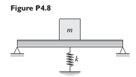
The beam shown in Figure P4.8 has been stiffened by the addition of a spring support. The steel beam is 3 ft long, 1 in thick, and 1 ft wide, and its mass is 3.8 slugs. The mass m is 40 slugs. Neglecting the mass of the beam.
- Compute the spring constant k necessary to reduce the static deflection to one-half its original value before the spring k was added.
Expert Solution & Answer
Want to see the full answer?
Check out a sample textbook solution
Students have asked these similar questions
3. A washing machine of mass 70kg operates at 1600 rpm. Find the maximum
stiffness of an isolator that provides 80 percent isolation. Assume that the damping
ratio of the isolator is 5 percent
Figure below shows a body of mass m attached to a spring of stiffness k. Find the differential equation for the displacement, x
3. Imagine a door which can swings into and out of a room. The door has a closer with a spring stiffness
of 71 N-m/rad and damping of 7.5 N-m-s/rad and mass moment of inertia of the door with respect to
the hinge is 20 kg-m?. If the door is held open and then let go from an angle of 50 degrees, how long will
the door continue to swing into and out of the room? How many times will it swings before it will
closed? Assume that the door is considered closed when the amplitude has decreased to 2.5 degrees.
Assume that small angle approximation holds, such that sin(theta) = theta.
%3D
Chapter 4 Solutions
System Dynamics
Ch. 4 - Prob. 4.1PCh. 4 - In the spring arrangement shown in Figure P4.2....Ch. 4 - In the arrangement shown in Figure P4.3, a cable...Ch. 4 - In the spring arrangement shown in Figure P4.4,...Ch. 4 - For the system shown in Figure P4.5, assume that...Ch. 4 - The two stepped solid cylinders in Figure P4.6...Ch. 4 - A table with four identical legs supports a...Ch. 4 - The beam shown in Figure P4.8 has been stiffened...Ch. 4 - Determine the equivalent spring constant of the...Ch. 4 - Compute the equivalent torsional spring constant...
Ch. 4 - Plot the spring force felt by the mass shown in...Ch. 4 - Calculate the expression for the natural frequency...Ch. 4 - Prob. 4.13PCh. 4 - Obtain the expression for the natural frequency of...Ch. 4 - 4.15 A connecting rod having a mass of 3.6 kg is...Ch. 4 - Calculate the expression for the natural frequency...Ch. 4 - For each of the systems shown in Figure P4.17, the...Ch. 4 - The mass m in Figure P4.18 is attached to a rigid...Ch. 4 - In the pulley system shown in Figure P4.19, the...Ch. 4 - Prob. 4.20PCh. 4 - Prob. 4.21PCh. 4 - Prob. 4.22PCh. 4 - In Figure P4.23, assume that the cylinder rolls...Ch. 4 - In Figure P4.24 when x1=x2=0 the springs are at...Ch. 4 - 4.25 In Figure P4.25 model the three shafts as...Ch. 4 - In Figure P4.26 when 1=2=0 the spring is at its...Ch. 4 - Prob. 4.27PCh. 4 - For the system shown in Figure P4.28, suppose that...Ch. 4 - For the system shown in Figure P4.29, suppose that...Ch. 4 - Prob. 4.30PCh. 4 - For Figure P4.31, the equilibrium position...Ch. 4 - Prob. 4.32PCh. 4 - Prob. 4.33PCh. 4 - 4.34 For Figure P4.34, assume that the cylinder...Ch. 4 - Use the Rayleigh method to obtain an expression...Ch. 4 - Prob. 4.36PCh. 4 - 4.37 Determine the natural frequency of the system...Ch. 4 - Determine the natural frequency of the system...Ch. 4 - Use Rayleigh's method to calculate the expression...Ch. 4 - Prob. 4.40PCh. 4 - Prob. 4.41PCh. 4 - Prob. 4.42PCh. 4 - The vibration of a motor mounted on the end of a...Ch. 4 - Prob. 4.44PCh. 4 - Prob. 4.45PCh. 4 - A certain cantilever beam vibrates at a frequency...Ch. 4 - Prob. 4.47PCh. 4 - 4.48 The static deflection of a cantilever beam is...Ch. 4 - Figure P4.49 shows a winch supported by a...Ch. 4 - Prob. 4.50PCh. 4 - Prob. 4.51PCh. 4 - Prob. 4.52PCh. 4 - 4.53 In Figure P4.53 a motor supplies a torque T...Ch. 4 - Derive the equation of motion for the lever system...Ch. 4 - Prob. 4.55PCh. 4 - Figure P4.56a shows a Houdaille damper, which is a...Ch. 4 - 4.57 Refer to Figure P4.57. Determine the...Ch. 4 - For the system shown in Figure P4.58, obtain the...Ch. 4 - Find the transfer function ZsXs for the system...Ch. 4 - Prob. 4.60PCh. 4 - Find the transfer function YsXs for the system...Ch. 4 - Prob. 4.62PCh. 4 - 4.63 In the system shown in Figure P4.63, the...Ch. 4 - Prob. 4.64PCh. 4 - Figure P4.65 shows a rack-and-pinion gear in which...Ch. 4 - Figure P4.66 shows a drive train with a spur-gear...Ch. 4 - Prob. 4.67PCh. 4 - Prob. 4.68PCh. 4 - Prob. 4.69PCh. 4 - Figure P4.70 shows a quarter-car model that...Ch. 4 - Prob. 4.71PCh. 4 - 4.72 Derive the equation of motion for the system...Ch. 4 - A boxcar moving at 1.3 m/s hits the shock absorber...Ch. 4 - For the systems shown in Figure P4.74, assume that...Ch. 4 - Refer to Figure P4.75a, which shows a ship’s...Ch. 4 - In this problem, we make all the same assumptions...Ch. 4 - Refer to Figure P4.79a, which shows a water tank...Ch. 4 - The “sky crane” shown on the text cover was a...Ch. 4 - Prob. 4.81PCh. 4 - Prob. 4.82PCh. 4 - Suppose a mass in moving with a speed 1 becomes...Ch. 4 - Consider the system shown in Figure 4.6.3. Suppose...Ch. 4 - Prob. 4.86PCh. 4 - Figure P4.87 shows a mass m with an attached...Ch. 4 - Figure P4.88 represents a drop forging process....Ch. 4 - Refer to Figure P4.89. A mass m drops from a...Ch. 4 - Prob. 4.90PCh. 4 - (a) Obtain the equations of motion of the system...Ch. 4 - Refer to part (a) of Problem 4.90. Use MATLAB to...Ch. 4 - Refer to Problem 4.91. Use MATLAB to obtain the...Ch. 4 - 4.94 (a) Obtain the equations of motion of the...Ch. 4 -
4.95 (a) Obtain the equations of motion of the...
Knowledge Booster


Learn more about
Need a deep-dive on the concept behind this application? Look no further. Learn more about this topic, mechanical-engineering and related others by exploring similar questions and additional content below.Similar questions
- A simple single degree of freedom model of a wheel mounted of a spring as shown in figure below .the friction in the system is such that the wheel rolls without slipping. Calculate the natural frequency of oscillation using the energy method .Assume that no energy is lost during the contact x(t) k m,J The rotation of the wheel (of radius r) is given by 0(t) and the linear displacement is denoted by x(t). The wheel has mass ( m) and moment of inertia (J) ,and the spring has stiffness (k ).arrow_forwardRefer to Figure Q2. A tray of mass mı is supported by 3 springs as shown in Figure 3(a). The natural frequency fa is 5.0Hz. An additional mass motor of m2 = 3.0kg (in OFF condition) is placed at the center on top of the mass, the natural frequency is observed to be 2.5Hz. a) Calculate the mass mı. The motor m2 is ON and it rotates at the speed of 600 rpm. Calculate: a) The transmissibility b) Attenuation c) Explain what will happen if the system run at Resonant Frequency m2 m1 Figure 2(a): Original system Figure 2(b): system with m2 addedarrow_forwardConsider the following spring system. Assume down is the positive direction. Write the stiffness matrix A 188 Displacement www my SE (₂ • Compute the displacements caused by the external forces f with spring constants e Earrow_forward
- Q1: The system shown has two masses. Beam of mass (Jo#m L² kg.m²) rotates about fixed point (O) and its free end is connected to disk rotates about fixed point (O₂). Consider all connecting links are massless and rigid. Find 1- The displacements of points A, B, and C in addition to the rotations of masses, all in terms of 0. 2- Find the equation of motion (EOM) in terms of 0. 3- What is the natural frequency of the system? 0 L/2 8 Energy methods A Jo=m L²2 L/2 Joz-m R² R C B C 128arrow_forward3. Consider the spring-mass system in an elevator that moves vertically. The natural length of the spring is as shown in the figure below, and at time t=0 the elevator starts moving with prescribed displacement y(t). Suppose that the relative displacement of the mass is x(t), i.e., its displacement with respect to the elevator. Assume mass m can only move vertically, the elevator is massless, and gravity is included. a. Derive the equation of motion of the mass using Newton's 2nd law. b. When is the mass in the elevator in a condition of effective "zero gravity"? y(t) x(t)arrow_forwardGiven the vibration system with multiple degree of freedom. For string 1, k1 = 10kN/m %3D For string 2, k2 = 20KN/m For string 3, k3 = 30 kN/m %3D mass = 500kg mass of the beam will not be consider. Solve for the following: i. Frequency j. Periodarrow_forward
- 2. Consider the following compound pendulum, which consists of a thin rod attached to a pivot point 1/3 down its length, and has a thin disk of radius R attached to the end. Mass of the rod is m, and mass of the disk is me. Tasks: a. Find an Equation of Motion for rotational motion of the pendulum. Assume 0 <15° and apply the small angle approximation. b. Find the natural frequency w of this system. Report in terms of mr, ma, I, R, and g.arrow_forwardA beam of constant cross-section, made of a uniform material, is supported by two springs at the A and B ends. Both springs are given as constant k. The vertical oscillation period is 0.83 seconds if no object is placed on the beam. When an object with a mass of 50 kg is placed in the center of the beam, the vertical oscillation period increases to 1.52 seconds. Calculate the stiffness wich is k of both springs, and the mass of the beam.arrow_forwardDetermine the equations to find the nodal displacements using the finite element direct method for the system as shown below. Assume that all free nodes undergo translation in x (1 DOF at each node) and that external forces Fı and F2 are known. Nodes 3 and 4 are fixed. The spring constants are known to0. Assume +x is to the right. Derive all equations and apply boundary conditions-leave your answer in terms of all known variables Do not rename the nodes or elements! Node 3 Node 4 k F1 F2 U2 Node 2 Node 1arrow_forward
- The torsional system of Figure Q6 oscillates about the centre of the disc. A linear spring and a linear damper are attached to the disc at radius r. A linear damping element is also attached at the edge of the disc at radius R. For this system assume that r = 0.15 m, R = 0.25 m, mass of disc m = 5 kg, stiffness coefficient k = 1200 N/m, and damping coefficient c = 10 Ns/m. Set up the differential equation of motion for this mechanical system. k Fin с R Figure Q6 C Disc 0arrow_forward2. A fixed-fixed steel beam, of length 5 m, width 0.5 m, and thickness 0.1 m, carries an electric motor of mass 75 kg and speed 1200 rpm at its mid-span, as shown in Figure. A rotating force of magnitude P, = 5000 N is developed due to the unbalance in the motor. Find the amplitude of steady-state vibrations by disregarding the mass of the beam. What will be the amplitude if the mass of the beam is considered by replacing with a mass lumped at the center equal to 25% of actual distributed mass. Take E = 207 Gpa and y = 76.5 kN/m³ for steel Ans: 4.15*104 m (w/o beam's mass) and; 11.5*10-4 m (with beam's mass)arrow_forwardThe torsional system of Figure Q6 oscillates about the centre of the disc. A linear spring and a linear damper are attached to the disc at radius r. A linear damping element is also attached at the edge of the disc at radius R. For this system assume that r = 0.15 m, R = 0.25 m, mass of disc m = 5 kg, stiffness coefficient k = 1200 N/m, and damping coefficient c = 10 Ns/m. a) Set up the differential equation of motion for this mechanical system.arrow_forward
arrow_back_ios
SEE MORE QUESTIONS
arrow_forward_ios
Recommended textbooks for you
 Elements Of ElectromagneticsMechanical EngineeringISBN:9780190698614Author:Sadiku, Matthew N. O.Publisher:Oxford University Press
 Mechanics of Materials (10th Edition)Mechanical EngineeringISBN:9780134319650Author:Russell C. HibbelerPublisher:PEARSON
 Thermodynamics: An Engineering ApproachMechanical EngineeringISBN:9781259822674Author:Yunus A. Cengel Dr., Michael A. BolesPublisher:McGraw-Hill Education
 Control Systems EngineeringMechanical EngineeringISBN:9781118170519Author:Norman S. NisePublisher:WILEY
 Mechanics of Materials (MindTap Course List)Mechanical EngineeringISBN:9781337093347Author:Barry J. Goodno, James M. GerePublisher:Cengage Learning
 Engineering Mechanics: StaticsMechanical EngineeringISBN:9781118807330Author:James L. Meriam, L. G. Kraige, J. N. BoltonPublisher:WILEY
Elements Of Electromagnetics
Mechanical Engineering
ISBN:9780190698614
Author:Sadiku, Matthew N. O.
Publisher:Oxford University Press
Mechanics of Materials (10th Edition)
Mechanical Engineering
ISBN:9780134319650
Author:Russell C. Hibbeler
Publisher:PEARSON
Thermodynamics: An Engineering Approach
Mechanical Engineering
ISBN:9781259822674
Author:Yunus A. Cengel Dr., Michael A. Boles
Publisher:McGraw-Hill Education
Control Systems Engineering
Mechanical Engineering
ISBN:9781118170519
Author:Norman S. Nise
Publisher:WILEY
Mechanics of Materials (MindTap Course List)
Mechanical Engineering
ISBN:9781337093347
Author:Barry J. Goodno, James M. Gere
Publisher:Cengage Learning
Engineering Mechanics: Statics
Mechanical Engineering
ISBN:9781118807330
Author:James L. Meriam, L. G. Kraige, J. N. Bolton
Publisher:WILEY
Ch 2 - 2.2.2 Forced Undamped Oscillation; Author: Benjamin Drew;https://www.youtube.com/watch?v=6Tb7Rx-bCWE;License: Standard youtube license