
System Dynamics
3rd Edition
ISBN: 9780073398068
Author: III William J. Palm
Publisher: MCG
expand_more
expand_more
format_list_bulleted
Videos
Textbook Question
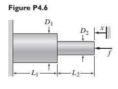
Chapter 4, Problem 4.6P
The two stepped solid cylinders in Figure P4.6 consist of the same material and have an axial force f applied to them. Determine the equivalent translational spring constant for this arrangement. (Hint: Are the two springs in series or in parallel?)
Expert Solution & Answer
Want to see the full answer?
Check out a sample textbook solution
Students have asked these similar questions
For this problem, take a look at Figure 2. Assume that the rod is massless, perfectly rigid, and pivoted at point P.
When the rod is perfectly horizontal, the angle 0 = 0, the displacement y = 0, and the spring is in neither tension
nor compression. Gravity acts on the system (e.g. on mass M). We assume that y is a small displacement. A mass
M is attached at the end of the rod.
k
Schen
a
0
a
F
The equation of motion for the system can be derived to be:
a
4aM0+ ak0 =-F-2Mg
T
y
M
Your tasks:
A. Transform the rotational equation of motion, which is in 0, given above, to another variable, y, which is zero
at the static equilibrium position.
B. Represent the mechanical system in state space form. Using MATLAB or a calculator (just say what you used),
calculate the eigenvalues of your A matrix for the following system parameters: a = 0.25 [m], M = 1 [kg], k =
16 [N/m], and F = 0 [N]. What do the eigenvalues say about the stability of the system?
C. Derive the response of the system in the…
Three springs with different spring
constants are connected as shown below.
You are going to use spring elements to
simulate this system. Suppose that the
spring constants of the first, second and
third elements are k1=3,410 N/m,
k2=3,160 N/m and k3=3,380 N/m,
respectively. Two horizontal forces are
applied to the system (as shown) at nodes.
2 and 3. Find the displacement of node 3
and write your answer in mm (millimetre).
Hint: Write your answer with 5 decimal
places. For example if you calculated the
value 1.2345678, then rounding off to 5
decimal places yields 1.23457 and that is
the value you need to type in the answer
box.
U₁=0
(1)
F₂ = 2N
U₂ = ?
F3 = -1N
(2)
M
U3 = ?
(3)
U4 = 0
tion sho
4-30
4-26. Graphically position the links for the box truck,
used to load supplies onto airplanes, as shown in
Figure P4.26. Then reposition the links as the lower
sliding pin moves 0.5 m toward the cab. Determine
the resulting linear displacement of any point on the
cargo box.
actuator needs to retract.
2 m
1.5 m
1.5 m
3 m
3 m
Chapter 4 Solutions
System Dynamics
Ch. 4 - Prob. 4.1PCh. 4 - In the spring arrangement shown in Figure P4.2....Ch. 4 - In the arrangement shown in Figure P4.3, a cable...Ch. 4 - In the spring arrangement shown in Figure P4.4,...Ch. 4 - For the system shown in Figure P4.5, assume that...Ch. 4 - The two stepped solid cylinders in Figure P4.6...Ch. 4 - A table with four identical legs supports a...Ch. 4 - The beam shown in Figure P4.8 has been stiffened...Ch. 4 - Determine the equivalent spring constant of the...Ch. 4 - Compute the equivalent torsional spring constant...
Ch. 4 - Plot the spring force felt by the mass shown in...Ch. 4 - Calculate the expression for the natural frequency...Ch. 4 - Prob. 4.13PCh. 4 - Obtain the expression for the natural frequency of...Ch. 4 - 4.15 A connecting rod having a mass of 3.6 kg is...Ch. 4 - Calculate the expression for the natural frequency...Ch. 4 - For each of the systems shown in Figure P4.17, the...Ch. 4 - The mass m in Figure P4.18 is attached to a rigid...Ch. 4 - In the pulley system shown in Figure P4.19, the...Ch. 4 - Prob. 4.20PCh. 4 - Prob. 4.21PCh. 4 - Prob. 4.22PCh. 4 - In Figure P4.23, assume that the cylinder rolls...Ch. 4 - In Figure P4.24 when x1=x2=0 the springs are at...Ch. 4 - 4.25 In Figure P4.25 model the three shafts as...Ch. 4 - In Figure P4.26 when 1=2=0 the spring is at its...Ch. 4 - Prob. 4.27PCh. 4 - For the system shown in Figure P4.28, suppose that...Ch. 4 - For the system shown in Figure P4.29, suppose that...Ch. 4 - Prob. 4.30PCh. 4 - For Figure P4.31, the equilibrium position...Ch. 4 - Prob. 4.32PCh. 4 - Prob. 4.33PCh. 4 - 4.34 For Figure P4.34, assume that the cylinder...Ch. 4 - Use the Rayleigh method to obtain an expression...Ch. 4 - Prob. 4.36PCh. 4 - 4.37 Determine the natural frequency of the system...Ch. 4 - Determine the natural frequency of the system...Ch. 4 - Use Rayleigh's method to calculate the expression...Ch. 4 - Prob. 4.40PCh. 4 - Prob. 4.41PCh. 4 - Prob. 4.42PCh. 4 - The vibration of a motor mounted on the end of a...Ch. 4 - Prob. 4.44PCh. 4 - Prob. 4.45PCh. 4 - A certain cantilever beam vibrates at a frequency...Ch. 4 - Prob. 4.47PCh. 4 - 4.48 The static deflection of a cantilever beam is...Ch. 4 - Figure P4.49 shows a winch supported by a...Ch. 4 - Prob. 4.50PCh. 4 - Prob. 4.51PCh. 4 - Prob. 4.52PCh. 4 - 4.53 In Figure P4.53 a motor supplies a torque T...Ch. 4 - Derive the equation of motion for the lever system...Ch. 4 - Prob. 4.55PCh. 4 - Figure P4.56a shows a Houdaille damper, which is a...Ch. 4 - 4.57 Refer to Figure P4.57. Determine the...Ch. 4 - For the system shown in Figure P4.58, obtain the...Ch. 4 - Find the transfer function ZsXs for the system...Ch. 4 - Prob. 4.60PCh. 4 - Find the transfer function YsXs for the system...Ch. 4 - Prob. 4.62PCh. 4 - 4.63 In the system shown in Figure P4.63, the...Ch. 4 - Prob. 4.64PCh. 4 - Figure P4.65 shows a rack-and-pinion gear in which...Ch. 4 - Figure P4.66 shows a drive train with a spur-gear...Ch. 4 - Prob. 4.67PCh. 4 - Prob. 4.68PCh. 4 - Prob. 4.69PCh. 4 - Figure P4.70 shows a quarter-car model that...Ch. 4 - Prob. 4.71PCh. 4 - 4.72 Derive the equation of motion for the system...Ch. 4 - A boxcar moving at 1.3 m/s hits the shock absorber...Ch. 4 - For the systems shown in Figure P4.74, assume that...Ch. 4 - Refer to Figure P4.75a, which shows a ship’s...Ch. 4 - In this problem, we make all the same assumptions...Ch. 4 - Refer to Figure P4.79a, which shows a water tank...Ch. 4 - The “sky crane” shown on the text cover was a...Ch. 4 - Prob. 4.81PCh. 4 - Prob. 4.82PCh. 4 - Suppose a mass in moving with a speed 1 becomes...Ch. 4 - Consider the system shown in Figure 4.6.3. Suppose...Ch. 4 - Prob. 4.86PCh. 4 - Figure P4.87 shows a mass m with an attached...Ch. 4 - Figure P4.88 represents a drop forging process....Ch. 4 - Refer to Figure P4.89. A mass m drops from a...Ch. 4 - Prob. 4.90PCh. 4 - (a) Obtain the equations of motion of the system...Ch. 4 - Refer to part (a) of Problem 4.90. Use MATLAB to...Ch. 4 - Refer to Problem 4.91. Use MATLAB to obtain the...Ch. 4 - 4.94 (a) Obtain the equations of motion of the...Ch. 4 -
4.95 (a) Obtain the equations of motion of the...
Knowledge Booster


Learn more about
Need a deep-dive on the concept behind this application? Look no further. Learn more about this topic, mechanical-engineering and related others by exploring similar questions and additional content below.Similar questions
- Q1: The system shown has two masses. Beam of mass (Jo#m L² kg.m²) rotates about fixed point (O) and its free end is connected to disk rotates about fixed point (O₂). Consider all connecting links are massless and rigid. Find 1- The displacements of points A, B, and C in addition to the rotations of masses, all in terms of 0. 2- Find the equation of motion (EOM) in terms of 0. 3- What is the natural frequency of the system? 0 L/2 8 Energy methods A Jo=m L²2 L/2 Joz-m R² R C B C 128arrow_forwardFor this problem, take a look at Figure 2 below. A disk with uniformly distributed mass m, radius R, and center of mass at point O is connected to a combination of springs at point P, which are then connected to a fixed wall. The disk rolls without slipping at point Q along an inclined plane that is at an angle a from the horizontal. Gravity acts in the vertical direction (towards the bottom of the page). ₁ is the linear coordinate of the point O along the inclined plane. The positive direction of ₁ is as shown. When the springs are undeflected, *₁ = 0. An angle , about the instant center of rotation, is shown. You may assume that the motion (and therefore angle ) is small. puny m Massless structure between springs R Figure 2: System schematic. Your tasks: A Draw the FBD for the disk. Don't forget the forces at point Q B Derive the equation of motion with as the dynamic variable. Be sure to put it in input-output standard form (inputs and constant forces on the right, things related to…arrow_forwardFind the equation of the following spring system. shaft k. disk -k,0 Jarrow_forward
- Three rigid bodies (Nodes 2, 3, and 4) are connected by five springs as shown below. Assume that the bodies can only undergo translation in the horizontal direction. Horizontal force P2=1000 N and P4=2000 N is applied to Elements 2 and 4, respectively. The spring constants in (N/mm) are given as: kı=100, k2=250, k3=300, k4=700, and ks=200. Nodes 1 and 5 are fixed. Determine the nodal displacements and reaction forces at the walls. Show all the work by deriving each equation and moving equations in matrix form and then applying BC's and solving. Do not rename the nodes or elements! 3arrow_forwardFind the equivalent spring constant spring constant of the system. Say, k1 = 20 lb/in, k2 = 35 lb/in, k3=18 lb/in,k4 = 50 lb/in, k5 = 45 lb/inarrow_forwardFor the system shown in below figure, determine the equivalent spring constant in the direction of ϴ.arrow_forward
- EHide blocks The two springs (AB) and (AC) are shown, in figure (a) below, in their original unstretched position. After the application. of a force F, the stretched position is shown in figure (b). The stiffness of spring (AC) is k(AC) = 200 lb/ft. The stiffness of the spring (AB), k(AB), is unknown. What would be the stretched length in spring (AB)? B 3. KAB 3 ft Kac- 200 !by 2ft wwarrow_forwardEHide blocks The two springs (AB) and (AC) are shown, in figure (a) below, in their original unstretched position. After the application. of a force F, the stretched position is shown in figure (b). The stiffness of spring (AC) is k(AC) = 200 lb/ft. The stiffness of the spring (AB), k(AB), is unknown. What would be the stretched length in spring (AB)? 8. ft KAB 3 ft 2f+ Kac- 200 y 2F4 24+ [a) wwarrow_forwardSuppose the four legs of Sitting on abe are Chair You identical this Scm springs. when you on Chair the chau's downwatd. what Constant of each is spring Spring? D Now Suppose that the Seae has only One leg. This leg is made by. tonnectin all the four spings in line when you sit it, the chair goes Scm downward. what is the Spring a on Constant of each spring ? (note): You owń uweight / mass for calculation' if you want to get numericlal Values Should use your as answer? Shot on vivo S1 00 AI Triple Cameraarrow_forward
- For each of the systems shown in Figure P4.52, the input is the force f andthe outputs are the displacements x1 and x2 of the masses. The equilibriumpositions with f = 0 correspond to x1 = x2 = 0. Neglect any friction betweenthe masses and the surface. Derive the equations of motion of the systems.arrow_forwardP4.8 Determine the rotational speed of link 3 of the mechanism given in figure P4.8 for the position shown. Use a complex numbers approacharrow_forwardIn the mechanical system in the figure, a rigid rod is bedded at point P and has mass m at its end. can rotate vertically. At the other end of the rod, a spring (k) and a damper (c) are attached. Draw the Free-Body Diagram of the system, obtain the Equation of Motion (the vertical position of the ball We assume that the displacement x is very small and the bar is massless).arrow_forward
arrow_back_ios
SEE MORE QUESTIONS
arrow_forward_ios
Recommended textbooks for you
 Elements Of ElectromagneticsMechanical EngineeringISBN:9780190698614Author:Sadiku, Matthew N. O.Publisher:Oxford University Press
 Mechanics of Materials (10th Edition)Mechanical EngineeringISBN:9780134319650Author:Russell C. HibbelerPublisher:PEARSON
 Thermodynamics: An Engineering ApproachMechanical EngineeringISBN:9781259822674Author:Yunus A. Cengel Dr., Michael A. BolesPublisher:McGraw-Hill Education
 Control Systems EngineeringMechanical EngineeringISBN:9781118170519Author:Norman S. NisePublisher:WILEY
 Mechanics of Materials (MindTap Course List)Mechanical EngineeringISBN:9781337093347Author:Barry J. Goodno, James M. GerePublisher:Cengage Learning
 Engineering Mechanics: StaticsMechanical EngineeringISBN:9781118807330Author:James L. Meriam, L. G. Kraige, J. N. BoltonPublisher:WILEY
Elements Of Electromagnetics
Mechanical Engineering
ISBN:9780190698614
Author:Sadiku, Matthew N. O.
Publisher:Oxford University Press
Mechanics of Materials (10th Edition)
Mechanical Engineering
ISBN:9780134319650
Author:Russell C. Hibbeler
Publisher:PEARSON
Thermodynamics: An Engineering Approach
Mechanical Engineering
ISBN:9781259822674
Author:Yunus A. Cengel Dr., Michael A. Boles
Publisher:McGraw-Hill Education
Control Systems Engineering
Mechanical Engineering
ISBN:9781118170519
Author:Norman S. Nise
Publisher:WILEY
Mechanics of Materials (MindTap Course List)
Mechanical Engineering
ISBN:9781337093347
Author:Barry J. Goodno, James M. Gere
Publisher:Cengage Learning
Engineering Mechanics: Statics
Mechanical Engineering
ISBN:9781118807330
Author:James L. Meriam, L. G. Kraige, J. N. Bolton
Publisher:WILEY
Mechanical SPRING DESIGN Strategy and Restrictions in Under 15 Minutes!; Author: Less Boring Lectures;https://www.youtube.com/watch?v=dsWQrzfQt3s;License: Standard Youtube License