
System Dynamics
3rd Edition
ISBN: 9780073398068
Author: III William J. Palm
Publisher: MCG
expand_more
expand_more
format_list_bulleted
Videos
Textbook Question
Chapter 4, Problem 4.79P
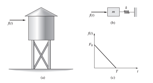
Refer to Figure P4.79a, which shows a water tank subjected to a blast force

Expert Solution & Answer
Want to see the full answer?
Check out a sample textbook solution
Students have asked these similar questions
4.13. Derive the differential equation of motion of the system shown in Fig. P4.1.
Obtain the steady state solution of the absolute motion of the mass. Also
obtain the displacement of the mass with respect to the moving base.
For this system, let m=3 kg, k1 =k2 = 1350 N/m, c= 40 N s/m, and
y=0.04 sin 15t. The initial conditions are such that xo =5 mm and io =0.
Determine the displacement, velocity, and acceleration of the mass after time
t =1s.
y = Y, sin @,1
k1
in
k2
m
Fig. P4.1
Q4/ For the figure below the spring is used to stop a 10
kg package. If the maximum deflection in the spring is 70
mm, (a) the total work of the system in the figure below
is:
8m/s
H=0,25
/K=400N/m
10kg
500m
0-30
(b): The total work when
theta =0 equal to: *
Three springs with different spring
constants are connected as shown below.
You are going to use spring elements to
simulate this system. Suppose that the
spring constants of the first, second and
third elements are k1=3,410 N/m,
k2=3,160 N/m and k3=3,380 N/m,
respectively. Two horizontal forces are
applied to the system (as shown) at nodes.
2 and 3. Find the displacement of node 3
and write your answer in mm (millimetre).
Hint: Write your answer with 5 decimal
places. For example if you calculated the
value 1.2345678, then rounding off to 5
decimal places yields 1.23457 and that is
the value you need to type in the answer
box.
U₁=0
(1)
F₂ = 2N
U₂ = ?
F3 = -1N
(2)
M
U3 = ?
(3)
U4 = 0
Chapter 4 Solutions
System Dynamics
Ch. 4 - Prob. 4.1PCh. 4 - In the spring arrangement shown in Figure P4.2....Ch. 4 - In the arrangement shown in Figure P4.3, a cable...Ch. 4 - In the spring arrangement shown in Figure P4.4,...Ch. 4 - For the system shown in Figure P4.5, assume that...Ch. 4 - The two stepped solid cylinders in Figure P4.6...Ch. 4 - A table with four identical legs supports a...Ch. 4 - The beam shown in Figure P4.8 has been stiffened...Ch. 4 - Determine the equivalent spring constant of the...Ch. 4 - Compute the equivalent torsional spring constant...
Ch. 4 - Plot the spring force felt by the mass shown in...Ch. 4 - Calculate the expression for the natural frequency...Ch. 4 - Prob. 4.13PCh. 4 - Obtain the expression for the natural frequency of...Ch. 4 - 4.15 A connecting rod having a mass of 3.6 kg is...Ch. 4 - Calculate the expression for the natural frequency...Ch. 4 - For each of the systems shown in Figure P4.17, the...Ch. 4 - The mass m in Figure P4.18 is attached to a rigid...Ch. 4 - In the pulley system shown in Figure P4.19, the...Ch. 4 - Prob. 4.20PCh. 4 - Prob. 4.21PCh. 4 - Prob. 4.22PCh. 4 - In Figure P4.23, assume that the cylinder rolls...Ch. 4 - In Figure P4.24 when x1=x2=0 the springs are at...Ch. 4 - 4.25 In Figure P4.25 model the three shafts as...Ch. 4 - In Figure P4.26 when 1=2=0 the spring is at its...Ch. 4 - Prob. 4.27PCh. 4 - For the system shown in Figure P4.28, suppose that...Ch. 4 - For the system shown in Figure P4.29, suppose that...Ch. 4 - Prob. 4.30PCh. 4 - For Figure P4.31, the equilibrium position...Ch. 4 - Prob. 4.32PCh. 4 - Prob. 4.33PCh. 4 - 4.34 For Figure P4.34, assume that the cylinder...Ch. 4 - Use the Rayleigh method to obtain an expression...Ch. 4 - Prob. 4.36PCh. 4 - 4.37 Determine the natural frequency of the system...Ch. 4 - Determine the natural frequency of the system...Ch. 4 - Use Rayleigh's method to calculate the expression...Ch. 4 - Prob. 4.40PCh. 4 - Prob. 4.41PCh. 4 - Prob. 4.42PCh. 4 - The vibration of a motor mounted on the end of a...Ch. 4 - Prob. 4.44PCh. 4 - Prob. 4.45PCh. 4 - A certain cantilever beam vibrates at a frequency...Ch. 4 - Prob. 4.47PCh. 4 - 4.48 The static deflection of a cantilever beam is...Ch. 4 - Figure P4.49 shows a winch supported by a...Ch. 4 - Prob. 4.50PCh. 4 - Prob. 4.51PCh. 4 - Prob. 4.52PCh. 4 - 4.53 In Figure P4.53 a motor supplies a torque T...Ch. 4 - Derive the equation of motion for the lever system...Ch. 4 - Prob. 4.55PCh. 4 - Figure P4.56a shows a Houdaille damper, which is a...Ch. 4 - 4.57 Refer to Figure P4.57. Determine the...Ch. 4 - For the system shown in Figure P4.58, obtain the...Ch. 4 - Find the transfer function ZsXs for the system...Ch. 4 - Prob. 4.60PCh. 4 - Find the transfer function YsXs for the system...Ch. 4 - Prob. 4.62PCh. 4 - 4.63 In the system shown in Figure P4.63, the...Ch. 4 - Prob. 4.64PCh. 4 - Figure P4.65 shows a rack-and-pinion gear in which...Ch. 4 - Figure P4.66 shows a drive train with a spur-gear...Ch. 4 - Prob. 4.67PCh. 4 - Prob. 4.68PCh. 4 - Prob. 4.69PCh. 4 - Figure P4.70 shows a quarter-car model that...Ch. 4 - Prob. 4.71PCh. 4 - 4.72 Derive the equation of motion for the system...Ch. 4 - A boxcar moving at 1.3 m/s hits the shock absorber...Ch. 4 - For the systems shown in Figure P4.74, assume that...Ch. 4 - Refer to Figure P4.75a, which shows a ship’s...Ch. 4 - In this problem, we make all the same assumptions...Ch. 4 - Refer to Figure P4.79a, which shows a water tank...Ch. 4 - The “sky crane” shown on the text cover was a...Ch. 4 - Prob. 4.81PCh. 4 - Prob. 4.82PCh. 4 - Suppose a mass in moving with a speed 1 becomes...Ch. 4 - Consider the system shown in Figure 4.6.3. Suppose...Ch. 4 - Prob. 4.86PCh. 4 - Figure P4.87 shows a mass m with an attached...Ch. 4 - Figure P4.88 represents a drop forging process....Ch. 4 - Refer to Figure P4.89. A mass m drops from a...Ch. 4 - Prob. 4.90PCh. 4 - (a) Obtain the equations of motion of the system...Ch. 4 - Refer to part (a) of Problem 4.90. Use MATLAB to...Ch. 4 - Refer to Problem 4.91. Use MATLAB to obtain the...Ch. 4 - 4.94 (a) Obtain the equations of motion of the...Ch. 4 -
4.95 (a) Obtain the equations of motion of the...
Knowledge Booster


Learn more about
Need a deep-dive on the concept behind this application? Look no further. Learn more about this topic, mechanical-engineering and related others by exploring similar questions and additional content below.Similar questions
- For each of the systems shown in Figure P4.52, the input is the force f andthe outputs are the displacements x1 and x2 of the masses. The equilibriumpositions with f = 0 correspond to x1 = x2 = 0. Neglect any friction betweenthe masses and the surface. Derive the equations of motion of the systems.arrow_forwardTwo carts with negligible rolling friction are connected as shown in Figure (1b). An input force u(t) is applied. The masses of the two carts are M, and M, and their displacements are x(t) and q(t), respectively. The carts are connected by a spring k and a damper b. Answer the following questions: (b) By using Newton's Second Law, derive two mathematical equations that describe the motion of the two carts. Hence derive the following two transfer functions: G,(s) = S) U(s) (c) x(1) 9(t) k M, M2 u(t) Figure (1b)arrow_forward(b) A system of mass rotation rod has been run at = 40 rad/s as shown in Figure Q1. The system has the following data, (i) (ii) Mass Mass A Mass B Mass C Weigh 1.2 kg 1.8 kg Mc Radius 1.135 m 0.822 m Re Angle 113.4° 48.8° вс Find counterweight mass-radius product and its angular location needed to balance the system. Distinguish the relationship between mass, radius and angle for counterweight mass system.arrow_forward
- Figure P3.40 illustrates a pendulum with a base that moves horizontally. Thisis a simple model of an overhead crane carrying a suspended load with cables.The load mass is m, the cable length is L, and the base acceleration is a(t).Assuming that the cable acts like a rigid rod, derive the equation of motion interms of ? with a(t) as the input.arrow_forwardFor the scotch yoke mechanism shown in the figure P4.1, the horizontal position of link 4 canbe described as x = 3 cos (50t + 40°). Determine the displacement of link 4 during theinterval of 3.8 to 4.7 s.arrow_forwardP3.3: Reduce Fig. below to open loop form. R G, G2 G. HA H1arrow_forward
- Chapter 07, Problem 027 Z Your answer is partially correct. Try again. A spring and block are in the arrangement of the figure. When the block is pulled out to x = +4.0 cm, we must apply a force of magnitude 370N to hold it there. We pull the block to x = 11.0 cm and then release it. How much work does the spring do on the block when the block moves from x, = +5.0 cm to (a) x = +4.0 cm, (b) x = -4.0 cm, (c) x= -5.0 cm, and (d) x = -10.0 cm? x=0 Block F= 0 attached elleeee to spring (a) x positive F, negative (b) ugen/shared/assignment/test/aglist.uni?id=.. x negative 9:34 PM search A ENG 4/4/2021 ASUS 13) 1ghome f10 snd 17 4 7. 00 16 3.arrow_forwardA slider-crank mechanism is used to impart motion to the base of a spring-mass-damper system, as shown in Figure (P3.1). Approximating the base motion y(t) as a series of harmonic functions, drive the equation of motion and find the response (natural frequency, damping ratio) of the mass for m = 1 kg, c = 10 N-s/m, k = 100 N/m, r = 10 cm, 1 = 1 m, and o = 100 rad/s. x(t) k/2 WWW 0 = ot m www k/2 Fig. P3.1arrow_forwardQ4/ For the figure below the spring is used to stop a 10 kg package. If the maximum deflection in the spring is 70 mm, (a) the total work of the system in the figure below is: 8m/s Hk=0,25 /K=400N/m 10kg 500m 0-30arrow_forward
- 3. Consider the spring-mass system in an elevator that moves vertically. The natural length of the spring is as shown in the figure below, and at time t=0 the elevator starts moving with prescribed displacement y(t). Suppose that the relative displacement of the mass is x(t), i.e., its displacement with respect to the elevator. Assume mass m can only move vertically, the elevator is massless, and gravity is included. a. Derive the equation of motion of the mass using Newton's 2nd law. b. When is the mass in the elevator in a condition of effective "zero gravity"? y(t) x(t)arrow_forwardUse the energy method to deriving the equations of motion for systems in Fig. 3, 4. Then calculate the resulting displacements due to the application of 1 N force.arrow_forward(a) A body of mass m, controlled by an elastic system, is given a displacement x. Derive an expression for the periodic frequency, n, of linear motion of the elastic system 1 n = Hz 1 Hz where ő is the static deflection in metres under the load, mg. (b) Figure TQ3.3 shows a suspended pendulum from a fixed pivot at O. The pendulum consists of a bar B, of mass 1kg, and block C of mass 6kg. The centre of gravity G1 and G2 of B and C are at distance 150mm and 375mm from 0. The radius of gyration of B and C, each about its own centre of gravity, are respectively 100mm and 25mm. A light spring is attached to the pendulum at point P, 200mm from 0, and is anchored at a fixed point, Q. When the Pendulum is in equilibrium, the line OG,PG2 is at 45° from the vertical and the angle OPQ is 90°. The spring has a stiffness of 700N/m. Calculate the natural frequency of the pendulum for small oscillations about the equilibrium position. 45° 0-150 0-20 Ig N G2 f0-3750 Y6g N Figure TQ3.3arrow_forward
arrow_back_ios
SEE MORE QUESTIONS
arrow_forward_ios
Recommended textbooks for you
 Elements Of ElectromagneticsMechanical EngineeringISBN:9780190698614Author:Sadiku, Matthew N. O.Publisher:Oxford University Press
 Mechanics of Materials (10th Edition)Mechanical EngineeringISBN:9780134319650Author:Russell C. HibbelerPublisher:PEARSON
 Thermodynamics: An Engineering ApproachMechanical EngineeringISBN:9781259822674Author:Yunus A. Cengel Dr., Michael A. BolesPublisher:McGraw-Hill Education
 Control Systems EngineeringMechanical EngineeringISBN:9781118170519Author:Norman S. NisePublisher:WILEY
 Mechanics of Materials (MindTap Course List)Mechanical EngineeringISBN:9781337093347Author:Barry J. Goodno, James M. GerePublisher:Cengage Learning
 Engineering Mechanics: StaticsMechanical EngineeringISBN:9781118807330Author:James L. Meriam, L. G. Kraige, J. N. BoltonPublisher:WILEY
Elements Of Electromagnetics
Mechanical Engineering
ISBN:9780190698614
Author:Sadiku, Matthew N. O.
Publisher:Oxford University Press
Mechanics of Materials (10th Edition)
Mechanical Engineering
ISBN:9780134319650
Author:Russell C. Hibbeler
Publisher:PEARSON
Thermodynamics: An Engineering Approach
Mechanical Engineering
ISBN:9781259822674
Author:Yunus A. Cengel Dr., Michael A. Boles
Publisher:McGraw-Hill Education
Control Systems Engineering
Mechanical Engineering
ISBN:9781118170519
Author:Norman S. Nise
Publisher:WILEY
Mechanics of Materials (MindTap Course List)
Mechanical Engineering
ISBN:9781337093347
Author:Barry J. Goodno, James M. Gere
Publisher:Cengage Learning
Engineering Mechanics: Statics
Mechanical Engineering
ISBN:9781118807330
Author:James L. Meriam, L. G. Kraige, J. N. Bolton
Publisher:WILEY
Mechanical SPRING DESIGN Strategy and Restrictions in Under 15 Minutes!; Author: Less Boring Lectures;https://www.youtube.com/watch?v=dsWQrzfQt3s;License: Standard Youtube License