
System Dynamics
3rd Edition
ISBN: 9780073398068
Author: III William J. Palm
Publisher: MCG
expand_more
expand_more
format_list_bulleted
Concept explainers
Videos
Textbook Question
thumb_up100%
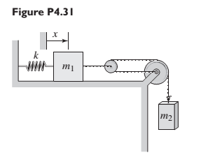
Chapter 4, Problem 4.31P
For Figure P4.31, the equilibrium position corresponds to
Expert Solution & Answer
Want to see the full answer?
Check out a sample textbook solution
Students have asked these similar questions
Three masses are attached to a uniform meter stick, as shown in figure. The mass of the meter stick is 150.0 g and the masses to the left of the fulcrum are m1 = 50 kg, m2 = 75 kg, and m3 that balances the system when it is attached at the right end of the sticky, and the normal reaction force at the fulcrum when the system is balanced. Also, find the mass m3.
2. The 6-kg frame AC and 4-kg uniform slender bar
AB of length / is free to slide along a smooth fixed
horizontal rod.
a. Find the tension in the wire BC for a static
case where the frame and bar are
stationary.
b. Now, with the the 80 N force applied find
the tension in the wire BC.
60°
to Q
B
60°
-80 N
-x
(a) Revisit the problem and solve for the cable forces TAD, TAC, and reaction force components 0,
Oy, and O₂ by invoking the cross-product formulation of moment equilibrium about point A. (b) An
alternative and powerful approach involves summing moments about a line the line OD. Start with the
vector equation of moment equilibrium about point O (since it lies on OD) and project this equation
along the line OD to solve for the cable tension TAC. Do not solve for any additional reactions.
0.8 m
X
1.6m
Z
D
1.6 m
2
1.IM
D
2m
A
B
y
F = (5î - 12 k) KN
Chapter 4 Solutions
System Dynamics
Ch. 4 - Prob. 4.1PCh. 4 - In the spring arrangement shown in Figure P4.2....Ch. 4 - In the arrangement shown in Figure P4.3, a cable...Ch. 4 - In the spring arrangement shown in Figure P4.4,...Ch. 4 - For the system shown in Figure P4.5, assume that...Ch. 4 - The two stepped solid cylinders in Figure P4.6...Ch. 4 - A table with four identical legs supports a...Ch. 4 - The beam shown in Figure P4.8 has been stiffened...Ch. 4 - Determine the equivalent spring constant of the...Ch. 4 - Compute the equivalent torsional spring constant...
Ch. 4 - Plot the spring force felt by the mass shown in...Ch. 4 - Calculate the expression for the natural frequency...Ch. 4 - Prob. 4.13PCh. 4 - Obtain the expression for the natural frequency of...Ch. 4 - 4.15 A connecting rod having a mass of 3.6 kg is...Ch. 4 - Calculate the expression for the natural frequency...Ch. 4 - For each of the systems shown in Figure P4.17, the...Ch. 4 - The mass m in Figure P4.18 is attached to a rigid...Ch. 4 - In the pulley system shown in Figure P4.19, the...Ch. 4 - Prob. 4.20PCh. 4 - Prob. 4.21PCh. 4 - Prob. 4.22PCh. 4 - In Figure P4.23, assume that the cylinder rolls...Ch. 4 - In Figure P4.24 when x1=x2=0 the springs are at...Ch. 4 - 4.25 In Figure P4.25 model the three shafts as...Ch. 4 - In Figure P4.26 when 1=2=0 the spring is at its...Ch. 4 - Prob. 4.27PCh. 4 - For the system shown in Figure P4.28, suppose that...Ch. 4 - For the system shown in Figure P4.29, suppose that...Ch. 4 - Prob. 4.30PCh. 4 - For Figure P4.31, the equilibrium position...Ch. 4 - Prob. 4.32PCh. 4 - Prob. 4.33PCh. 4 - 4.34 For Figure P4.34, assume that the cylinder...Ch. 4 - Use the Rayleigh method to obtain an expression...Ch. 4 - Prob. 4.36PCh. 4 - 4.37 Determine the natural frequency of the system...Ch. 4 - Determine the natural frequency of the system...Ch. 4 - Use Rayleigh's method to calculate the expression...Ch. 4 - Prob. 4.40PCh. 4 - Prob. 4.41PCh. 4 - Prob. 4.42PCh. 4 - The vibration of a motor mounted on the end of a...Ch. 4 - Prob. 4.44PCh. 4 - Prob. 4.45PCh. 4 - A certain cantilever beam vibrates at a frequency...Ch. 4 - Prob. 4.47PCh. 4 - 4.48 The static deflection of a cantilever beam is...Ch. 4 - Figure P4.49 shows a winch supported by a...Ch. 4 - Prob. 4.50PCh. 4 - Prob. 4.51PCh. 4 - Prob. 4.52PCh. 4 - 4.53 In Figure P4.53 a motor supplies a torque T...Ch. 4 - Derive the equation of motion for the lever system...Ch. 4 - Prob. 4.55PCh. 4 - Figure P4.56a shows a Houdaille damper, which is a...Ch. 4 - 4.57 Refer to Figure P4.57. Determine the...Ch. 4 - For the system shown in Figure P4.58, obtain the...Ch. 4 - Find the transfer function ZsXs for the system...Ch. 4 - Prob. 4.60PCh. 4 - Find the transfer function YsXs for the system...Ch. 4 - Prob. 4.62PCh. 4 - 4.63 In the system shown in Figure P4.63, the...Ch. 4 - Prob. 4.64PCh. 4 - Figure P4.65 shows a rack-and-pinion gear in which...Ch. 4 - Figure P4.66 shows a drive train with a spur-gear...Ch. 4 - Prob. 4.67PCh. 4 - Prob. 4.68PCh. 4 - Prob. 4.69PCh. 4 - Figure P4.70 shows a quarter-car model that...Ch. 4 - Prob. 4.71PCh. 4 - 4.72 Derive the equation of motion for the system...Ch. 4 - A boxcar moving at 1.3 m/s hits the shock absorber...Ch. 4 - For the systems shown in Figure P4.74, assume that...Ch. 4 - Refer to Figure P4.75a, which shows a ship’s...Ch. 4 - In this problem, we make all the same assumptions...Ch. 4 - Refer to Figure P4.79a, which shows a water tank...Ch. 4 - The “sky crane” shown on the text cover was a...Ch. 4 - Prob. 4.81PCh. 4 - Prob. 4.82PCh. 4 - Suppose a mass in moving with a speed 1 becomes...Ch. 4 - Consider the system shown in Figure 4.6.3. Suppose...Ch. 4 - Prob. 4.86PCh. 4 - Figure P4.87 shows a mass m with an attached...Ch. 4 - Figure P4.88 represents a drop forging process....Ch. 4 - Refer to Figure P4.89. A mass m drops from a...Ch. 4 - Prob. 4.90PCh. 4 - (a) Obtain the equations of motion of the system...Ch. 4 - Refer to part (a) of Problem 4.90. Use MATLAB to...Ch. 4 - Refer to Problem 4.91. Use MATLAB to obtain the...Ch. 4 - 4.94 (a) Obtain the equations of motion of the...Ch. 4 -
4.95 (a) Obtain the equations of motion of the...
Knowledge Booster


Learn more about
Need a deep-dive on the concept behind this application? Look no further. Learn more about this topic, mechanical-engineering and related others by exploring similar questions and additional content below.Similar questions
- or 5, 2. You have a massless spring of force constant 64 N/m, but it is wound tightly enough that you must apply 16 N of force to it before it begins to stretch. You attach a 12 kg mass to one end of the spring. The other end is fixed in place above the mass (e.g. it is clamped to the room's ceiling). A second mass of 1.0 kg is connected to the bottom of this first mass via a thin string of negligible mass. The system is initially in equilibrium, but then the string connecting the smaller mass suddenly snaps. 2.1 What is the initial acceleration of the spring-mass system? 2.2. What is the amplitude of oscillation for this system? 2.3 What would be the period of oscillation for this system? 2.4 Determine the maximum value of the kinetic energy of the mass still connected to the spring. Assume negligible damping.arrow_forwardQ4. (а) Explain the meaning of spring force and the graph of spring force against positionarrow_forwardA pendulum is made up of a spring with a mass attached to the end. The spring is arranged to lie in a straight line, by wrapping the spring around a massless bar. The equilibrium length of the bar is “l”. Using lagrange’s equations, find the equations of motion.arrow_forward
- Draw a free-body diagram for this system.arrow_forwardThere are two parallel forces and two pure moments in the figure. What distance "d" must separate the forces in order for the system to be in equilibrium? F = 9 N, M1 = 15 N-m, M2 = 69 N-m, = 60 degrees, a = 1 m, b = 1 m, c = 2 marrow_forwardQ2) Consider a mass (m=5 kg) connected to a massless rod of length (L=2 m) to swing about point O, as shown in Figure (2). The mass is also connected to a spring of spring constant (k=10 N/m). The other end of the spring is connected to a pivot. The unstretched length of the spring is 1 m. Find the equation of motion of the L=2 m system. m-5 kg 3 m k-10 N/m Figure 2 wwarrow_forward
- Q1: The system shown has two masses. Beam of mass (Jo#m L² kg.m²) rotates about fixed point (O) and its free end is connected to disk rotates about fixed point (O₂). Consider all connecting links are massless and rigid. Find 1- The displacements of points A, B, and C in addition to the rotations of masses, all in terms of 0. 2- Find the equation of motion (EOM) in terms of 0. 3- What is the natural frequency of the system? 0 L/2 8 Energy methods A Jo=m L²2 L/2 Joz-m R² R C B C 128arrow_forwardQ2) Consider a mass (m=5 kg) connected to a massless rod of length (L=2 m) to swing about point O, as shown in Figure (2). The mass is also connected to a spring of spring constant (k=10 N/m). The other end of the spring is connected to a pivot. The unstretched length of the spring is 1 m. Find the equation of motion of the L-2 m system. m-5 kg 3 m k=10 N/marrow_forwardQ2) Consider a mass (m=5 kg) connected to a massless rod of length (L=2 m) to swing about point O, as shown in Figure (2). The mass is also connected to a spring of spring constant (k=10 N/m). The other end of the spring is connected to a pivot. The unstretched length of the spring is 1 m. Find the equation of motion of the L-2 m system. polar coordinates (r-0). m-5 kg 3 m k-10 N/m Figure 2arrow_forward
- Given that the slot (for the cord) in the cylinder with 17.6 kg in the figure below has a negligible effect on Ic, find the time required for C to move 3.7 m down the incline if 0 = 55°. R = 1.4 m,r = 0.6 m, and u = 0.11. Cord R Figure is from "Engineering Mechanic An Introduction to Dynamics", McGill and King.arrow_forwardFor each of the systems shown in Figure P4.52, the input is the force f andthe outputs are the displacements x1 and x2 of the masses. The equilibriumpositions with f = 0 correspond to x1 = x2 = 0. Neglect any friction betweenthe masses and the surface. Derive the equations of motion of the systems.arrow_forwardExample 1: Four masses m1, m2, m3, m4 are 200 kg. 300 kg. 240 kg and 260 kg, respectively. The corresponding radii of rotation are 0.2, 0.15, 0.25 and 0.3 meters, respectively, and the angles between successive masses are 45°, 75° and 135°. Find the position and magnitude of the balance mass required, if its radius of rotation is set to 0.2 m.arrow_forward
arrow_back_ios
SEE MORE QUESTIONS
arrow_forward_ios
Recommended textbooks for you
 Elements Of ElectromagneticsMechanical EngineeringISBN:9780190698614Author:Sadiku, Matthew N. O.Publisher:Oxford University Press
 Mechanics of Materials (10th Edition)Mechanical EngineeringISBN:9780134319650Author:Russell C. HibbelerPublisher:PEARSON
 Thermodynamics: An Engineering ApproachMechanical EngineeringISBN:9781259822674Author:Yunus A. Cengel Dr., Michael A. BolesPublisher:McGraw-Hill Education
 Control Systems EngineeringMechanical EngineeringISBN:9781118170519Author:Norman S. NisePublisher:WILEY
 Mechanics of Materials (MindTap Course List)Mechanical EngineeringISBN:9781337093347Author:Barry J. Goodno, James M. GerePublisher:Cengage Learning
 Engineering Mechanics: StaticsMechanical EngineeringISBN:9781118807330Author:James L. Meriam, L. G. Kraige, J. N. BoltonPublisher:WILEY
Elements Of Electromagnetics
Mechanical Engineering
ISBN:9780190698614
Author:Sadiku, Matthew N. O.
Publisher:Oxford University Press
Mechanics of Materials (10th Edition)
Mechanical Engineering
ISBN:9780134319650
Author:Russell C. Hibbeler
Publisher:PEARSON
Thermodynamics: An Engineering Approach
Mechanical Engineering
ISBN:9781259822674
Author:Yunus A. Cengel Dr., Michael A. Boles
Publisher:McGraw-Hill Education
Control Systems Engineering
Mechanical Engineering
ISBN:9781118170519
Author:Norman S. Nise
Publisher:WILEY
Mechanics of Materials (MindTap Course List)
Mechanical Engineering
ISBN:9781337093347
Author:Barry J. Goodno, James M. Gere
Publisher:Cengage Learning
Engineering Mechanics: Statics
Mechanical Engineering
ISBN:9781118807330
Author:James L. Meriam, L. G. Kraige, J. N. Bolton
Publisher:WILEY
Ch 2 - 2.2.2 Forced Undamped Oscillation; Author: Benjamin Drew;https://www.youtube.com/watch?v=6Tb7Rx-bCWE;License: Standard youtube license