
System Dynamics
3rd Edition
ISBN: 9780073398068
Author: III William J. Palm
Publisher: MCG
expand_more
expand_more
format_list_bulleted
Videos
Textbook Question
Chapter 4, Problem 4.66P
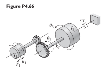
Figure P4.66 shows a drive train with a spur-gear pair. The first shaft turns N times faster than the second shaft. Develop a model of the system including the elasticity of the second shaft. Assume the first shaft is rigid, and neglect the gear and shaft masses. The input is the applied torque
Expert Solution & Answer
Want to see the full answer?
Check out a sample textbook solution
Students have asked these similar questions
Q2
A maximum torque of 6.75 kNm can be supplied to the constant diameter steel (G = 80 GPa)
line shaft by a motor as shown in Figure Q2. At the current normal operation condition, three
machines are driven by gear B, C and D on the shaft and they require torques of 3.x kNm,
1.5y kNm and 1.0z kNm, respectively. Parameter x, y, and z are given by:
X=0
Y=0
Z=2
|
(b)
Calculate the rotation of gear D with respect to the coupling at A if the coupling and
gears are spaced at 2 m intervals at the current normal operation condition.
B
-Bearing
D
Figure Q2
For the double slider mechanism shown in the following figure, the crank OA rotates at a uniform speed of 100 rad/s CW.
we need to find the required torque for the crank, if two forces act at sliders B and C as shown in the figure. (P = 2KN, Q = 1KN).
OA = 30 cm, AB = AC = 100 cm.
mB = mC = 1 Kg. Neglect other links weights.
The velocity of slip of slider B in m/s2 = Answer 1
Choose...
The velocity of slip of slider C in m/s2 =
Answer 2
Choose...
The acceleration of slip of slider B in m/s2 =
Answer 3
Choose...
The acceleration of slip of slider C in m/s2 =
Answer 4
Choose...
The magnitude of required torque for the crank in N.m =
Answer 5
Choose...
A motor with a torque of 37.26N/m and a speed of 120°/sec rotates a robotic arm that consists
of two gears (one with a diameter of 4cm and 8 gear teeth and the other with a diameter of
10cm and 24 gear teeth). The arm is attached to the gears, and the arm must lift approximately
50 pounds of weight. The arm needs to lift about 1m distance. Find the following?
1) Find the amount of force required to lift the 50 pounds of weight
2) Find the power needed to lift 50 pounds.
3) Find the gear ratio for the gears to work properly.
DC Motor
Worn Gear
Gear
50 Ibs
Chapter 4 Solutions
System Dynamics
Ch. 4 - Prob. 4.1PCh. 4 - In the spring arrangement shown in Figure P4.2....Ch. 4 - In the arrangement shown in Figure P4.3, a cable...Ch. 4 - In the spring arrangement shown in Figure P4.4,...Ch. 4 - For the system shown in Figure P4.5, assume that...Ch. 4 - The two stepped solid cylinders in Figure P4.6...Ch. 4 - A table with four identical legs supports a...Ch. 4 - The beam shown in Figure P4.8 has been stiffened...Ch. 4 - Determine the equivalent spring constant of the...Ch. 4 - Compute the equivalent torsional spring constant...
Ch. 4 - Plot the spring force felt by the mass shown in...Ch. 4 - Calculate the expression for the natural frequency...Ch. 4 - Prob. 4.13PCh. 4 - Obtain the expression for the natural frequency of...Ch. 4 - 4.15 A connecting rod having a mass of 3.6 kg is...Ch. 4 - Calculate the expression for the natural frequency...Ch. 4 - For each of the systems shown in Figure P4.17, the...Ch. 4 - The mass m in Figure P4.18 is attached to a rigid...Ch. 4 - In the pulley system shown in Figure P4.19, the...Ch. 4 - Prob. 4.20PCh. 4 - Prob. 4.21PCh. 4 - Prob. 4.22PCh. 4 - In Figure P4.23, assume that the cylinder rolls...Ch. 4 - In Figure P4.24 when x1=x2=0 the springs are at...Ch. 4 - 4.25 In Figure P4.25 model the three shafts as...Ch. 4 - In Figure P4.26 when 1=2=0 the spring is at its...Ch. 4 - Prob. 4.27PCh. 4 - For the system shown in Figure P4.28, suppose that...Ch. 4 - For the system shown in Figure P4.29, suppose that...Ch. 4 - Prob. 4.30PCh. 4 - For Figure P4.31, the equilibrium position...Ch. 4 - Prob. 4.32PCh. 4 - Prob. 4.33PCh. 4 - 4.34 For Figure P4.34, assume that the cylinder...Ch. 4 - Use the Rayleigh method to obtain an expression...Ch. 4 - Prob. 4.36PCh. 4 - 4.37 Determine the natural frequency of the system...Ch. 4 - Determine the natural frequency of the system...Ch. 4 - Use Rayleigh's method to calculate the expression...Ch. 4 - Prob. 4.40PCh. 4 - Prob. 4.41PCh. 4 - Prob. 4.42PCh. 4 - The vibration of a motor mounted on the end of a...Ch. 4 - Prob. 4.44PCh. 4 - Prob. 4.45PCh. 4 - A certain cantilever beam vibrates at a frequency...Ch. 4 - Prob. 4.47PCh. 4 - 4.48 The static deflection of a cantilever beam is...Ch. 4 - Figure P4.49 shows a winch supported by a...Ch. 4 - Prob. 4.50PCh. 4 - Prob. 4.51PCh. 4 - Prob. 4.52PCh. 4 - 4.53 In Figure P4.53 a motor supplies a torque T...Ch. 4 - Derive the equation of motion for the lever system...Ch. 4 - Prob. 4.55PCh. 4 - Figure P4.56a shows a Houdaille damper, which is a...Ch. 4 - 4.57 Refer to Figure P4.57. Determine the...Ch. 4 - For the system shown in Figure P4.58, obtain the...Ch. 4 - Find the transfer function ZsXs for the system...Ch. 4 - Prob. 4.60PCh. 4 - Find the transfer function YsXs for the system...Ch. 4 - Prob. 4.62PCh. 4 - 4.63 In the system shown in Figure P4.63, the...Ch. 4 - Prob. 4.64PCh. 4 - Figure P4.65 shows a rack-and-pinion gear in which...Ch. 4 - Figure P4.66 shows a drive train with a spur-gear...Ch. 4 - Prob. 4.67PCh. 4 - Prob. 4.68PCh. 4 - Prob. 4.69PCh. 4 - Figure P4.70 shows a quarter-car model that...Ch. 4 - Prob. 4.71PCh. 4 - 4.72 Derive the equation of motion for the system...Ch. 4 - A boxcar moving at 1.3 m/s hits the shock absorber...Ch. 4 - For the systems shown in Figure P4.74, assume that...Ch. 4 - Refer to Figure P4.75a, which shows a ship’s...Ch. 4 - In this problem, we make all the same assumptions...Ch. 4 - Refer to Figure P4.79a, which shows a water tank...Ch. 4 - The “sky crane” shown on the text cover was a...Ch. 4 - Prob. 4.81PCh. 4 - Prob. 4.82PCh. 4 - Suppose a mass in moving with a speed 1 becomes...Ch. 4 - Consider the system shown in Figure 4.6.3. Suppose...Ch. 4 - Prob. 4.86PCh. 4 - Figure P4.87 shows a mass m with an attached...Ch. 4 - Figure P4.88 represents a drop forging process....Ch. 4 - Refer to Figure P4.89. A mass m drops from a...Ch. 4 - Prob. 4.90PCh. 4 - (a) Obtain the equations of motion of the system...Ch. 4 - Refer to part (a) of Problem 4.90. Use MATLAB to...Ch. 4 - Refer to Problem 4.91. Use MATLAB to obtain the...Ch. 4 - 4.94 (a) Obtain the equations of motion of the...Ch. 4 -
4.95 (a) Obtain the equations of motion of the...
Knowledge Booster


Learn more about
Need a deep-dive on the concept behind this application? Look no further. Learn more about this topic, mechanical-engineering and related others by exploring similar questions and additional content below.Similar questions
- A maximum torque of 6.75 kNm can be supplied to the constant diameter steel (G= 80 GPa) line shaft by a motor as shown in Figure Q2. At the current normal operation condition, three machines are driven by gear B, C and D on the shaft and they require torques of 3.x kNm, 1.5y kNm and 1.0z kNm, respectively. Parameter x, y, and z are given by: Q2 X=0 Y=0 Z=2 Considering the maximum torque can be supplied by motor, determine the minimum diameter required if the maximum shearing stress in the shaft is limited to 100 MPa. Round your answer to the nearest whole number. (a) -Bearing D Figure Q2arrow_forwardTwo rotating parallel shafts AB and CD are connected through spur gears E and F as shown by Figure Q4. The diameters of shafts AB and CD are respectively 30 mm and 35 mm, while the pitch radii of gears E and Fare 50 mm and 125 mm respectively. The bearings B, C and Dallow free rotation of the shafts and the motor provides power to rotate the shafts.arrow_forwardAn electric motor is accelerating a 250 kg load with acceleration of 1.2 m/s? througha gear box as shown Figure Q1(b). The rope that carries the load and spiral spring are encircled on a pulley with diameter 1.2m. Gear box ratio is 0. 1 and gear box efficiency is 100%, while gear box equivalent moment inertia is 5.55 km?. Neglect friction effect in this drive system and assume spiral spring force is X newtonCalculate the torque of the motor needed to bring up the load with acceleration1.2 m/s?.arrow_forward
- For the double slider mechanism shown in the following figure, the crank OA rotates at a uniform speed of 24 rad/s ccw. we need to find the required torque for the crank, if two forces act at sliders B and C as shown in the figure. (P = 4 kN, Q = 2 kN). OA = 10 cm, AB = AC = 70 cm. mg = mc = 5 Kg. Neglect other links weights. (5) (2) (3) B (4) (6) C 45° X. The velocity of slip of slider B in m/s² = Choose.. + The velocity of slip of slider C in m/s? = Choose... + The acceleration of slip of slider B in m/s² = Choose.. + The acceleration of slip of slider C in m/s² = Choose.. + The magnitude of required torque for the crank in N.m = Choose..arrow_forwardFor the double slider mechanism shown in the following figure, the crank OA rotates at a uniform speed of 200 rad/s CCW. we need to find the required torque for the crank, if two forces act at sliders B and C as shown in the figure. (P = 2 kN, Q = 4 kN). OA = 20 cm, AB = AC = 80 cm. mg =10 kg, mc = 5 Kg. Neglect other links weights. (3) (2)45° (5) B (4) X The velocity of slip of slider B in m/s? = Choose... + The velocity of slip of slider C in m/s? = Choose... + The acceleration of slip of slider B in m/s2 = Choose... + The acceleration of slip of slider C in m/s? = Choose... + The magnitude of required torque for the crank in N.m = Choose... +arrow_forwardTwo rotating parallel shafts AB and CD are connected through spur gears E and Fas shown by Figure Q4. The diameters of shafts AB and CD are respectively 30 mm and 35 mm, while the pitch radii of gears E and F are 50 mm and 125 mm respectively. The bearings B, C and D allow free rotation of the shafts and the motor provides power to rotate the shafts.arrow_forward
- I In this problem, consider the figure below. A disk with radius r, mass m, and moment of inertia of Io about the point O is on an inclined plane, with the translational coordinates and y and rotation angle 0, as shown. The direction of gravity is shown, and the incline angle is a. A constant input torque is applied at the point O in the direction shown, and it is opposed by a damping torque from a bearing with value co in the direction shown. The point P represents a point of instantaneous contact, rolling without slipping. Your tasks: Direction of Gravity M(t) co 0 P x Mass: m Figure 2: System schematic. Moment of Inertia about 0: lo a: Incline Angle A Draw the FBD for the disk. B Derive the equation of motion with the rotation angle as the dynamic variable. 0 C Take the Laplace transform, and solve for (s), letting the initial conditions be 0(0) = 0 and (0) = 0. Remember that a constant is a step function for a one-sided Laplace transform. D Given your expression for (s), find the…arrow_forwardUse the energy method to deriving the equations of motion for systems in Fig. 3, 4. Then calculate the resulting displacements due to the application of 1 N force.arrow_forwardA shaft, shown in Figure Q4, 1.4 m long carries four eccentric loads A, B, C and D, spaced at 0.00 m, 0.45 m, 0.75 m and 1.4 m from the end. The loads are respectively 7.5 kg, 11 kg, 15 kg and 6 kg, and eccentricities are 36 mm, 48 mm, 54 mm and 96 mm. The directions of the eccentricities of B, C and D relative to A are 600, 2000 and 2700. The shaft is carried in bearings E and F, which are 0.175 m and 1.0 m from A, E being between A and B.arrow_forward
- A spur pinion of pitch diameter 50 mm rotates at 200 rad/s and transmits 3 kW power. The pressure angle of the tooth of the pinion is 20°. find the total force exerted by a tooth of the pinion on other gear?arrow_forwardFor this problem, take a look at Figure 2 below. A disk with uniformly distributed mass m, radius R, and center of mass at point O is connected to a combination of springs at point P, which are then connected to a fixed wall. The disk rolls without slipping at point Q along an inclined plane that is at an angle a from the horizontal. Gravity acts in the vertical direction (towards the bottom of the page). ₁ is the linear coordinate of the point O along the inclined plane. The positive direction of ₁ is as shown. When the springs are undeflected, *₁ = 0. An angle , about the instant center of rotation, is shown. You may assume that the motion (and therefore angle ) is small. puny m Massless structure between springs R Figure 2: System schematic. Your tasks: A Draw the FBD for the disk. Don't forget the forces at point Q B Derive the equation of motion with as the dynamic variable. Be sure to put it in input-output standard form (inputs and constant forces on the right, things related to…arrow_forwardThree springs with different spring constants are connected as shown below. You are going to use spring elements to simulate this system. Suppose that the spring constants of the first, second and third elements are k1=3,410 N/m, k2=3,160 N/m and k3=3,380 N/m, respectively. Two horizontal forces are applied to the system (as shown) at nodes. 2 and 3. Find the displacement of node 3 and write your answer in mm (millimetre). Hint: Write your answer with 5 decimal places. For example if you calculated the value 1.2345678, then rounding off to 5 decimal places yields 1.23457 and that is the value you need to type in the answer box. U₁=0 (1) F₂ = 2N U₂ = ? F3 = -1N (2) M U3 = ? (3) U4 = 0arrow_forward
arrow_back_ios
SEE MORE QUESTIONS
arrow_forward_ios
Recommended textbooks for you
 Elements Of ElectromagneticsMechanical EngineeringISBN:9780190698614Author:Sadiku, Matthew N. O.Publisher:Oxford University Press
 Mechanics of Materials (10th Edition)Mechanical EngineeringISBN:9780134319650Author:Russell C. HibbelerPublisher:PEARSON
 Thermodynamics: An Engineering ApproachMechanical EngineeringISBN:9781259822674Author:Yunus A. Cengel Dr., Michael A. BolesPublisher:McGraw-Hill Education
 Control Systems EngineeringMechanical EngineeringISBN:9781118170519Author:Norman S. NisePublisher:WILEY
 Mechanics of Materials (MindTap Course List)Mechanical EngineeringISBN:9781337093347Author:Barry J. Goodno, James M. GerePublisher:Cengage Learning
 Engineering Mechanics: StaticsMechanical EngineeringISBN:9781118807330Author:James L. Meriam, L. G. Kraige, J. N. BoltonPublisher:WILEY
Elements Of Electromagnetics
Mechanical Engineering
ISBN:9780190698614
Author:Sadiku, Matthew N. O.
Publisher:Oxford University Press
Mechanics of Materials (10th Edition)
Mechanical Engineering
ISBN:9780134319650
Author:Russell C. Hibbeler
Publisher:PEARSON
Thermodynamics: An Engineering Approach
Mechanical Engineering
ISBN:9781259822674
Author:Yunus A. Cengel Dr., Michael A. Boles
Publisher:McGraw-Hill Education
Control Systems Engineering
Mechanical Engineering
ISBN:9781118170519
Author:Norman S. Nise
Publisher:WILEY
Mechanics of Materials (MindTap Course List)
Mechanical Engineering
ISBN:9781337093347
Author:Barry J. Goodno, James M. Gere
Publisher:Cengage Learning
Engineering Mechanics: Statics
Mechanical Engineering
ISBN:9781118807330
Author:James L. Meriam, L. G. Kraige, J. N. Bolton
Publisher:WILEY
How to balance a see saw using moments example problem; Author: Engineer4Free;https://www.youtube.com/watch?v=d7tX37j-iHU;License: Standard Youtube License