
System Dynamics
3rd Edition
ISBN: 9780073398068
Author: III William J. Palm
Publisher: MCG
expand_more
expand_more
format_list_bulleted
Videos
Textbook Question
Chapter 4, Problem 4.2P
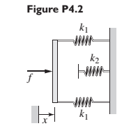
In the spring arrangement shown in Figure P4.2. the displacement x is caused by the applied force f. Assuming the system is in static equilibrium, sketch the plot of f versus x. Determine the equivalent spring constant
Expert Solution & Answer
Want to see the full answer?
Check out a sample textbook solution
Students have asked these similar questions
Three springs with different spring
constants are connected as shown below.
You are going to use spring elements to
simulate this system. Suppose that the
spring constants of the first, second and
third elements are k1=3,410 N/m,
k2=3,160 N/m and k3=3,380 N/m,
respectively. Two horizontal forces are
applied to the system (as shown) at nodes.
2 and 3. Find the displacement of node 3
and write your answer in mm (millimetre).
Hint: Write your answer with 5 decimal
places. For example if you calculated the
value 1.2345678, then rounding off to 5
decimal places yields 1.23457 and that is
the value you need to type in the answer
box.
U₁=0
(1)
F₂ = 2N
U₂ = ?
F3 = -1N
(2)
M
U3 = ?
(3)
U4 = 0
Q1: The system shown has two masses. Beam of mass (Jo#m L²
kg.m²) rotates about fixed point (O) and its free end is connected to
disk rotates about fixed point (O₂). Consider all connecting links are
massless and rigid. Find
1- The displacements of points A, B, and C in addition to the
rotations of masses, all in terms of 0.
2- Find the equation of motion (EOM) in terms of 0.
3- What is the natural frequency of the system?
0
L/2
8
Energy methods
A
Jo=m L²2
L/2
Joz-m R²
R
C
B
C
128
or
5,
2. You have a massless spring of force constant 64 N/m, but it is wound tightly enough that you must
apply 16 N of force to it before it begins to stretch. You attach a 12 kg mass to one end of the spring.
The other end is fixed in place above the mass (e.g. it is clamped to the room's ceiling). A second
mass of 1.0 kg is connected to the bottom of this first mass via a thin string of negligible mass. The
system is initially in equilibrium, but then the string connecting the smaller mass suddenly snaps.
2.1 What is the initial acceleration of the spring-mass system?
2.2. What is the amplitude of oscillation for this system?
2.3 What would be the period of oscillation for this system?
2.4 Determine the maximum value of the kinetic energy of the mass still connected to the spring.
Assume negligible damping.
Chapter 4 Solutions
System Dynamics
Ch. 4 - Prob. 4.1PCh. 4 - In the spring arrangement shown in Figure P4.2....Ch. 4 - In the arrangement shown in Figure P4.3, a cable...Ch. 4 - In the spring arrangement shown in Figure P4.4,...Ch. 4 - For the system shown in Figure P4.5, assume that...Ch. 4 - The two stepped solid cylinders in Figure P4.6...Ch. 4 - A table with four identical legs supports a...Ch. 4 - The beam shown in Figure P4.8 has been stiffened...Ch. 4 - Determine the equivalent spring constant of the...Ch. 4 - Compute the equivalent torsional spring constant...
Ch. 4 - Plot the spring force felt by the mass shown in...Ch. 4 - Calculate the expression for the natural frequency...Ch. 4 - Prob. 4.13PCh. 4 - Obtain the expression for the natural frequency of...Ch. 4 - 4.15 A connecting rod having a mass of 3.6 kg is...Ch. 4 - Calculate the expression for the natural frequency...Ch. 4 - For each of the systems shown in Figure P4.17, the...Ch. 4 - The mass m in Figure P4.18 is attached to a rigid...Ch. 4 - In the pulley system shown in Figure P4.19, the...Ch. 4 - Prob. 4.20PCh. 4 - Prob. 4.21PCh. 4 - Prob. 4.22PCh. 4 - In Figure P4.23, assume that the cylinder rolls...Ch. 4 - In Figure P4.24 when x1=x2=0 the springs are at...Ch. 4 - 4.25 In Figure P4.25 model the three shafts as...Ch. 4 - In Figure P4.26 when 1=2=0 the spring is at its...Ch. 4 - Prob. 4.27PCh. 4 - For the system shown in Figure P4.28, suppose that...Ch. 4 - For the system shown in Figure P4.29, suppose that...Ch. 4 - Prob. 4.30PCh. 4 - For Figure P4.31, the equilibrium position...Ch. 4 - Prob. 4.32PCh. 4 - Prob. 4.33PCh. 4 - 4.34 For Figure P4.34, assume that the cylinder...Ch. 4 - Use the Rayleigh method to obtain an expression...Ch. 4 - Prob. 4.36PCh. 4 - 4.37 Determine the natural frequency of the system...Ch. 4 - Determine the natural frequency of the system...Ch. 4 - Use Rayleigh's method to calculate the expression...Ch. 4 - Prob. 4.40PCh. 4 - Prob. 4.41PCh. 4 - Prob. 4.42PCh. 4 - The vibration of a motor mounted on the end of a...Ch. 4 - Prob. 4.44PCh. 4 - Prob. 4.45PCh. 4 - A certain cantilever beam vibrates at a frequency...Ch. 4 - Prob. 4.47PCh. 4 - 4.48 The static deflection of a cantilever beam is...Ch. 4 - Figure P4.49 shows a winch supported by a...Ch. 4 - Prob. 4.50PCh. 4 - Prob. 4.51PCh. 4 - Prob. 4.52PCh. 4 - 4.53 In Figure P4.53 a motor supplies a torque T...Ch. 4 - Derive the equation of motion for the lever system...Ch. 4 - Prob. 4.55PCh. 4 - Figure P4.56a shows a Houdaille damper, which is a...Ch. 4 - 4.57 Refer to Figure P4.57. Determine the...Ch. 4 - For the system shown in Figure P4.58, obtain the...Ch. 4 - Find the transfer function ZsXs for the system...Ch. 4 - Prob. 4.60PCh. 4 - Find the transfer function YsXs for the system...Ch. 4 - Prob. 4.62PCh. 4 - 4.63 In the system shown in Figure P4.63, the...Ch. 4 - Prob. 4.64PCh. 4 - Figure P4.65 shows a rack-and-pinion gear in which...Ch. 4 - Figure P4.66 shows a drive train with a spur-gear...Ch. 4 - Prob. 4.67PCh. 4 - Prob. 4.68PCh. 4 - Prob. 4.69PCh. 4 - Figure P4.70 shows a quarter-car model that...Ch. 4 - Prob. 4.71PCh. 4 - 4.72 Derive the equation of motion for the system...Ch. 4 - A boxcar moving at 1.3 m/s hits the shock absorber...Ch. 4 - For the systems shown in Figure P4.74, assume that...Ch. 4 - Refer to Figure P4.75a, which shows a ship’s...Ch. 4 - In this problem, we make all the same assumptions...Ch. 4 - Refer to Figure P4.79a, which shows a water tank...Ch. 4 - The “sky crane” shown on the text cover was a...Ch. 4 - Prob. 4.81PCh. 4 - Prob. 4.82PCh. 4 - Suppose a mass in moving with a speed 1 becomes...Ch. 4 - Consider the system shown in Figure 4.6.3. Suppose...Ch. 4 - Prob. 4.86PCh. 4 - Figure P4.87 shows a mass m with an attached...Ch. 4 - Figure P4.88 represents a drop forging process....Ch. 4 - Refer to Figure P4.89. A mass m drops from a...Ch. 4 - Prob. 4.90PCh. 4 - (a) Obtain the equations of motion of the system...Ch. 4 - Refer to part (a) of Problem 4.90. Use MATLAB to...Ch. 4 - Refer to Problem 4.91. Use MATLAB to obtain the...Ch. 4 - 4.94 (a) Obtain the equations of motion of the...Ch. 4 -
4.95 (a) Obtain the equations of motion of the...
Knowledge Booster


Learn more about
Need a deep-dive on the concept behind this application? Look no further. Learn more about this topic, mechanical-engineering and related others by exploring similar questions and additional content below.Similar questions
- Find the equivalent spring constant spring constant of the system. Say, k1 = 20 lb/in, k2 = 35 lb/in, k3=18 lb/in,k4 = 50 lb/in, k5 = 45 lb/inarrow_forwardFor each of the systems shown in Figure P4.52, the input is the force f andthe outputs are the displacements x1 and x2 of the masses. The equilibriumpositions with f = 0 correspond to x1 = x2 = 0. Neglect any friction betweenthe masses and the surface. Derive the equations of motion of the systems.arrow_forward2. Find the k equivalent of the system, if each spring has a spring constant of 20 lb/in except for the only spring on the bottom which has a spring constantant of 50 lb/in.arrow_forward
- Consider the system shown in the figure below. Assume that the massless rigid bars AB and AC are in horizontal and vertical positions respectively when the system is in static equilibrium. The vector g shows the direction of gravitational acceleration (assume g = 9.81 m/s2). Assuming m = 4 kg, a = 4 m, for the system to vibrate without instability, the stiffness k should be greater than: m a m A a a 2 19.62 N/m 0.00 N/m 39.24 N/m 29.43 N/m 9.81 N/m www O O O O Oarrow_forwardThe image below is of an arm in 90 degree elbow flexion holding an implement in the hand. SOLVE FOR THE TORQUE ABOUT THE ELBOW IN ORDER TO MAINTAIN EQUILIBRIUM. Here are the values. d1: 0.024m d2: 0.310m d3: 0.690m Fbarbell: 697N Farm: 74Narrow_forward2- Two mass-spring systems A & B both have stiffness of k-10 N/m. The mass of system A is twice the mass of system B (mA=2mg= 1 kg), which system will oscillate faster? Why? Support your answer with a plot.arrow_forward
- A mass weighing 4 pounds is attached to a spring whose spring constant is 36 lb/ft. Find the equation of motion.arrow_forwardQUESTION 3. Consider the mass-spring oscillator without friction: y" + y = 0. Suppose we add a force x(t) which corresponds to a push (to the left) of the mass as it oscillates. We will suppose the push is described by the function x(t) = -u(t – 2n) + u(t – (2n + a)) for some a > 2n which we are allowed to vary. (A small a will correspond to a short duration push and a large a to a long duration push). Here, u(t) is the unit step function. We are interested in solving the initial value problem y" + y = x(t), y(0) = 1, y'(0) = 0.arrow_forwardThe members of the mechanism are pin connected. The spring is unstretched when 0 = 0°. Neglect the mass of the links. A vertical force of 800 N acts at A. a. Draw how the virtual displacement on this mechanism would look like. b. Write down x and y coordinates as a function of the angle 0 with the respective derivative of the virtual displacements expressions. c. Write the virtual work equation d. Determine the angle 0 for equilibrium k = 6 kN/m 1 m 1 m 1 m 800 N Dwwwwarrow_forward
- k, k3 A В k2 What is the equivalent spring stiffness between the points A and B. If ki = 1 N/m, k2 =1 N/m. k3 = 2 N/m and k4 = 2 N/m A N/marrow_forwardProblem No 6 1.26 Find the equivalent spring constant of the system shown in Fig. 1.82. k F k k k FIGURE 1.82 Springs connected in series-parallelarrow_forwardProblem No 5 1.9 In Fig. 1.69, find the equivalent spring constant of the system in the direction of 0. k2 k3arrow_forward
arrow_back_ios
SEE MORE QUESTIONS
arrow_forward_ios
Recommended textbooks for you
 Elements Of ElectromagneticsMechanical EngineeringISBN:9780190698614Author:Sadiku, Matthew N. O.Publisher:Oxford University Press
 Mechanics of Materials (10th Edition)Mechanical EngineeringISBN:9780134319650Author:Russell C. HibbelerPublisher:PEARSON
 Thermodynamics: An Engineering ApproachMechanical EngineeringISBN:9781259822674Author:Yunus A. Cengel Dr., Michael A. BolesPublisher:McGraw-Hill Education
 Control Systems EngineeringMechanical EngineeringISBN:9781118170519Author:Norman S. NisePublisher:WILEY
 Mechanics of Materials (MindTap Course List)Mechanical EngineeringISBN:9781337093347Author:Barry J. Goodno, James M. GerePublisher:Cengage Learning
 Engineering Mechanics: StaticsMechanical EngineeringISBN:9781118807330Author:James L. Meriam, L. G. Kraige, J. N. BoltonPublisher:WILEY
Elements Of Electromagnetics
Mechanical Engineering
ISBN:9780190698614
Author:Sadiku, Matthew N. O.
Publisher:Oxford University Press
Mechanics of Materials (10th Edition)
Mechanical Engineering
ISBN:9780134319650
Author:Russell C. Hibbeler
Publisher:PEARSON
Thermodynamics: An Engineering Approach
Mechanical Engineering
ISBN:9781259822674
Author:Yunus A. Cengel Dr., Michael A. Boles
Publisher:McGraw-Hill Education
Control Systems Engineering
Mechanical Engineering
ISBN:9781118170519
Author:Norman S. Nise
Publisher:WILEY
Mechanics of Materials (MindTap Course List)
Mechanical Engineering
ISBN:9781337093347
Author:Barry J. Goodno, James M. Gere
Publisher:Cengage Learning
Engineering Mechanics: Statics
Mechanical Engineering
ISBN:9781118807330
Author:James L. Meriam, L. G. Kraige, J. N. Bolton
Publisher:WILEY
Mechanical SPRING DESIGN Strategy and Restrictions in Under 15 Minutes!; Author: Less Boring Lectures;https://www.youtube.com/watch?v=dsWQrzfQt3s;License: Standard Youtube License