
System Dynamics
3rd Edition
ISBN: 9780073398068
Author: III William J. Palm
Publisher: MCG
expand_more
expand_more
format_list_bulleted
Videos
Textbook Question
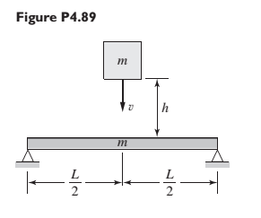
Chapter 4, Problem 4.89P
Refer to Figure P4.89. A mass m drops from a height h and hits and sticks to a simply supported beam of equal mass. Obtain an expression for the maximum deflection of the center of the beam. Your answer should be a function of h, g, m. and the beam stiffness k.
Expert Solution & Answer
Want to see the full answer?
Check out a sample textbook solution
Students have asked these similar questions
Q2: A particle is thrown at an angle of 30° with velocity of 36 kmph calculate its time of flight and
horizontal range.
Q3: A wire 10m long of cross section area 1.22 cm? elongates by 1.5 cm when 4.5 kg is suspended
from it find: 1. Stress 2. Strain 3. Youngs modulus of the wire
1. A beam with the triangular cross section of Figure P4.7 is of length L and madeof material with Young’s modulus E. It is built in at one end and loaded by a force Fin the x-direction at the other end. Find the two components of displacement at theloaded end.
1. The figure below shows a one-dimensional, horizontal beam of uniform-density in static equilibrium. The beam is supported
by a frictionless support at a point 1/3 of the way down its length (L). A rope running through a frictionless pulley is attached
to the far end of the beam. The mass of the beam per-unit-meter (m) is known, and the magnitude of the acceleration due to
gravity is g.
y
| 9
13
a) What is the total force due to the weight of the beam and where does it act?
b) Draw the free body diagram (FBD) of this beam.
c) Derive expressions for the vertical reaction force at the support (R) and the force applied to the end of the rope (F).
Your expressions should be in terms of L, m,, and g; that is, you should find Ry = f(L, mr, g) and F = f(L, mz.g).
Chapter 4 Solutions
System Dynamics
Ch. 4 - Prob. 4.1PCh. 4 - In the spring arrangement shown in Figure P4.2....Ch. 4 - In the arrangement shown in Figure P4.3, a cable...Ch. 4 - In the spring arrangement shown in Figure P4.4,...Ch. 4 - For the system shown in Figure P4.5, assume that...Ch. 4 - The two stepped solid cylinders in Figure P4.6...Ch. 4 - A table with four identical legs supports a...Ch. 4 - The beam shown in Figure P4.8 has been stiffened...Ch. 4 - Determine the equivalent spring constant of the...Ch. 4 - Compute the equivalent torsional spring constant...
Ch. 4 - Plot the spring force felt by the mass shown in...Ch. 4 - Calculate the expression for the natural frequency...Ch. 4 - Prob. 4.13PCh. 4 - Obtain the expression for the natural frequency of...Ch. 4 - 4.15 A connecting rod having a mass of 3.6 kg is...Ch. 4 - Calculate the expression for the natural frequency...Ch. 4 - For each of the systems shown in Figure P4.17, the...Ch. 4 - The mass m in Figure P4.18 is attached to a rigid...Ch. 4 - In the pulley system shown in Figure P4.19, the...Ch. 4 - Prob. 4.20PCh. 4 - Prob. 4.21PCh. 4 - Prob. 4.22PCh. 4 - In Figure P4.23, assume that the cylinder rolls...Ch. 4 - In Figure P4.24 when x1=x2=0 the springs are at...Ch. 4 - 4.25 In Figure P4.25 model the three shafts as...Ch. 4 - In Figure P4.26 when 1=2=0 the spring is at its...Ch. 4 - Prob. 4.27PCh. 4 - For the system shown in Figure P4.28, suppose that...Ch. 4 - For the system shown in Figure P4.29, suppose that...Ch. 4 - Prob. 4.30PCh. 4 - For Figure P4.31, the equilibrium position...Ch. 4 - Prob. 4.32PCh. 4 - Prob. 4.33PCh. 4 - 4.34 For Figure P4.34, assume that the cylinder...Ch. 4 - Use the Rayleigh method to obtain an expression...Ch. 4 - Prob. 4.36PCh. 4 - 4.37 Determine the natural frequency of the system...Ch. 4 - Determine the natural frequency of the system...Ch. 4 - Use Rayleigh's method to calculate the expression...Ch. 4 - Prob. 4.40PCh. 4 - Prob. 4.41PCh. 4 - Prob. 4.42PCh. 4 - The vibration of a motor mounted on the end of a...Ch. 4 - Prob. 4.44PCh. 4 - Prob. 4.45PCh. 4 - A certain cantilever beam vibrates at a frequency...Ch. 4 - Prob. 4.47PCh. 4 - 4.48 The static deflection of a cantilever beam is...Ch. 4 - Figure P4.49 shows a winch supported by a...Ch. 4 - Prob. 4.50PCh. 4 - Prob. 4.51PCh. 4 - Prob. 4.52PCh. 4 - 4.53 In Figure P4.53 a motor supplies a torque T...Ch. 4 - Derive the equation of motion for the lever system...Ch. 4 - Prob. 4.55PCh. 4 - Figure P4.56a shows a Houdaille damper, which is a...Ch. 4 - 4.57 Refer to Figure P4.57. Determine the...Ch. 4 - For the system shown in Figure P4.58, obtain the...Ch. 4 - Find the transfer function ZsXs for the system...Ch. 4 - Prob. 4.60PCh. 4 - Find the transfer function YsXs for the system...Ch. 4 - Prob. 4.62PCh. 4 - 4.63 In the system shown in Figure P4.63, the...Ch. 4 - Prob. 4.64PCh. 4 - Figure P4.65 shows a rack-and-pinion gear in which...Ch. 4 - Figure P4.66 shows a drive train with a spur-gear...Ch. 4 - Prob. 4.67PCh. 4 - Prob. 4.68PCh. 4 - Prob. 4.69PCh. 4 - Figure P4.70 shows a quarter-car model that...Ch. 4 - Prob. 4.71PCh. 4 - 4.72 Derive the equation of motion for the system...Ch. 4 - A boxcar moving at 1.3 m/s hits the shock absorber...Ch. 4 - For the systems shown in Figure P4.74, assume that...Ch. 4 - Refer to Figure P4.75a, which shows a ship’s...Ch. 4 - In this problem, we make all the same assumptions...Ch. 4 - Refer to Figure P4.79a, which shows a water tank...Ch. 4 - The “sky crane” shown on the text cover was a...Ch. 4 - Prob. 4.81PCh. 4 - Prob. 4.82PCh. 4 - Suppose a mass in moving with a speed 1 becomes...Ch. 4 - Consider the system shown in Figure 4.6.3. Suppose...Ch. 4 - Prob. 4.86PCh. 4 - Figure P4.87 shows a mass m with an attached...Ch. 4 - Figure P4.88 represents a drop forging process....Ch. 4 - Refer to Figure P4.89. A mass m drops from a...Ch. 4 - Prob. 4.90PCh. 4 - (a) Obtain the equations of motion of the system...Ch. 4 - Refer to part (a) of Problem 4.90. Use MATLAB to...Ch. 4 - Refer to Problem 4.91. Use MATLAB to obtain the...Ch. 4 - 4.94 (a) Obtain the equations of motion of the...Ch. 4 -
4.95 (a) Obtain the equations of motion of the...
Knowledge Booster


Learn more about
Need a deep-dive on the concept behind this application? Look no further. Learn more about this topic, mechanical-engineering and related others by exploring similar questions and additional content below.Similar questions
- An object with a mass of 0.5 kg is released at a distance of 2 m, the spring coefficient k = 100 N / m and the object is in the same direction after impact. If it is known to rebound on the road throughout; a) Find the maximum compression and maximum spring force in the spring. b) Find the rebound height if e = 0.5. (Assume that the spring behaves linearly during deformation, when the object leaves the spring, the spring regains its initial length (L) and energy is conserved during compression.) ① The object is 2 m above the arc and is at rest. ② The object is about to hit the spring. ③ It is the moment when the object compresses the spring as much as. ④ It is the moment when the spring is most compressed, the object is at rest at this moment. ⑤ It is the moment when the object loses contact with the spring. ⑥ The object is at the top h of the spring as a result of becomes immobile at distance.arrow_forwarda) The beam shown in Figure A2(a) is pin supported at A and roller supported at B. Find reactions at supports A and B. 30kN 10KN/m 40kNm 2m 2m 4m Figure A2(a) b) A truck of total mass 18tonne descends a hill with a gradient of 1 in 14, i.e. a vertical movement of 1m for each 14m of movement along the slope. During this motion, the truck experiences a rolling resistance to its motion of 900N. Whilst travelling at a velocity of 54km/h, its brakes are applied, and the truck is brought uniformly to rest in a distance of 112m. During this period of constant deceleration, it may be assumed that the rolling resistance remains constant at 900N, this being in addition to the retarding force applied by the brakes. Calculate for the truck whilst it is slowing down: a) The vertical height through which it descends. b) Its decrease in potential energy. c) Its initial velocity in m/s. d) Its decrease in kinetic energy. e) The work done against the rolling resistance.arrow_forwardMechanics of Solid An overhanging beam is loaded as shown in Figure Q1. (a) Sketch the free body diagram for the beam and determine the unknown reactions. (b) Sketch the shear force and bending moment diagrams for the beam. (c) Locate the location and the magnitude of maximum bending moment and zero shear force.arrow_forward
- mhm 4.31 System for Exercise 4.24 (left) and Exercise 4.25 (right). m, the force required to deflect the end, as is illustrated in Figure 4.32 is In Chapter 11 we are much smarter and are able to show that for a cantilever ЗЕЛ L3 X, 4.32 Cantilever beam subjected to a at the end. F = ere E is the modulus of elasticity, which is a property of the material used, I is area moment of inertia of the cross-section of the beam, and L is the length. If a mass m,is attached to the end of the beam, what is the equation of motion the vertical motion of the beam? If the length is doubled, what is the change in quency of the free vibration of the beam? =kX 2 Guieds x=0 F-XX F x = L Fig. 4.33 Rotatin 4.28. Referring the end of a ca elasticity of the length is L = 1 1. Determine t 2. Determine t @= 1000 r 4.29. Determin 1. On the sam 2. Identify the the part youarrow_forwardA long, thin, wire of uniform cross-section has Young's Modulus Y and mass density D. When laid horizontally on a bench its unstretched length is L. One end is attached to a fixed point and the rest of the wire is allowed to hang freely and vertically in the earth's gravitational field. Find the extension of the lowest end of the wire (i.e., the wire's length additional to L) due to gravitational force. The acceleration due to gravity is g.arrow_forwardA uniform rod PQ of mass mkg and length 4a, the end P of the rod is hinged to a point on the vertical wall. A particle of mass mis attached to the rod at Q. One end of a light inextensible string is attached to the rod at R, where PR=3a, and S is vertically above P. The rod rests horizontally in equilibrium on a vertical plane perpendicular to the wall and the tension in the string is T.arrow_forward
- Consider the impact of a 2 kg bird at the free end of an aircraft wing. The bird is moving at a speed of 10 m/s towards the aircraft. Speed of aircraft is 105 m. Model the aircraft wing as a beam of rectangular cross section having 3 m length, 0.05 m thickness and 0.5m width. During impact, compute a) the static equivalent force on the aircraft wing b)the maximum deflection of the wingarrow_forwardLearning Goal: To determine an I-beam's maximum bending moment, moment of inertia using the parallel-axis theorem, and the maximum stress at a given location using the flexure formula. As shown, I-beam ABC supports a sign that weighs S = 30 lb . The I-beam is 24 in. long and is further supported by a rod that is attached 18 in. from the wall. Assume that all forces acting on the I-beam act along its centroid and that the I-beam's weight is negligible. Let the dimensions of the I-beam be w = 4 in., g = 0.8 in., h = 2.9 in., j = 1 in., c = 6 in. c A ·a b B Part A - Free-body diagram of beam ABC S C H j- W h Before the problem can be analyzed, a free-body diagram must be drawn to understand the forces and reactions that act on the I-beam. Draw the free-body diagram of beam ABC. A free-body diagram includes the forces acting on the object, in this case the beam. Start your vectors at the black dots. You will not be graded on vector length. Ignore all reaction forces in the x direction, and…arrow_forwardA cantilever beam supports a 30KN point-load at position B and 25KN at position C. The beam is 10m long and x is the position along the beam from the free end at point C as shown in Figure Q5. 5. 25KN 30kN B 6m 4m 10m Figure Q5. (а) Draw the free body diagram of the beam, calculate the support reaction at point A and the bending moment MA. (b) Calculate the shear-force and bending-moment as a function of x both between A and B and between B and C. (c) Draw the shear force and bending moment diagrams of the beam.arrow_forward
- igure 2. Assume that the rod is massless, perfectly rigid, and pivoted at point P. When the rod is perfectly horizontal, the angle 0 = 0, the displacement y 0, and the springs are in neither tension nor compression. Gravity acts on the system (e.g. on mass M). We assume that y is a small displacement. A mass M is attached at the end of the rod. DE only 225 Your tasks: X k 0 3k a F a M y A Derive an equation of motion for the system in terms of the angular displacement 0, and its derivatives (you should not have y or its derivatives in this equation.) B Derive an equation of motion for the system in terms of the displacement y, and its derivatives (you should not have or its derivatives in this equation. C Assuming there is no external actuator force F acting on the system, write down the total energy H of the system in terms of 0,0 and element constants. Derive an expression for the time derivative H of the total energy. D Transform the equation from part B, which is in y, to another…arrow_forward5. A rod of length L, Young's modulus E, cross-sectional area A and mass density p is installed as shown. Suppose m = pAL and kL / EA =1. Find the equations of motion Open Question m www f(t) x=0 x = L/2 x= Larrow_forwardQ3. Fig Q3 shows a uniform cantilever beam of length L which is loaded by a linearly varying load: w(x) = wo where w is the load per unit length at the fixed end (x =0). L w(x) Fig Q3: A uniform cantilever beam (a) Using Ritz method, derive a two-term polynomial function to approximate the transverse displacement (u) of the beam. Total potential energy (TPE) for a beam under bending load is: TPE= EI d'u Jo 2 dx² -w(x)u dx where E is Young's modulus and I is second moment of area. (b) Calculate the bending moment at x = L based on Ritz solution.arrow_forward
arrow_back_ios
SEE MORE QUESTIONS
arrow_forward_ios
Recommended textbooks for you
 Elements Of ElectromagneticsMechanical EngineeringISBN:9780190698614Author:Sadiku, Matthew N. O.Publisher:Oxford University Press
 Mechanics of Materials (10th Edition)Mechanical EngineeringISBN:9780134319650Author:Russell C. HibbelerPublisher:PEARSON
 Thermodynamics: An Engineering ApproachMechanical EngineeringISBN:9781259822674Author:Yunus A. Cengel Dr., Michael A. BolesPublisher:McGraw-Hill Education
 Control Systems EngineeringMechanical EngineeringISBN:9781118170519Author:Norman S. NisePublisher:WILEY
 Mechanics of Materials (MindTap Course List)Mechanical EngineeringISBN:9781337093347Author:Barry J. Goodno, James M. GerePublisher:Cengage Learning
 Engineering Mechanics: StaticsMechanical EngineeringISBN:9781118807330Author:James L. Meriam, L. G. Kraige, J. N. BoltonPublisher:WILEY
Elements Of Electromagnetics
Mechanical Engineering
ISBN:9780190698614
Author:Sadiku, Matthew N. O.
Publisher:Oxford University Press
Mechanics of Materials (10th Edition)
Mechanical Engineering
ISBN:9780134319650
Author:Russell C. Hibbeler
Publisher:PEARSON
Thermodynamics: An Engineering Approach
Mechanical Engineering
ISBN:9781259822674
Author:Yunus A. Cengel Dr., Michael A. Boles
Publisher:McGraw-Hill Education
Control Systems Engineering
Mechanical Engineering
ISBN:9781118170519
Author:Norman S. Nise
Publisher:WILEY
Mechanics of Materials (MindTap Course List)
Mechanical Engineering
ISBN:9781337093347
Author:Barry J. Goodno, James M. Gere
Publisher:Cengage Learning
Engineering Mechanics: Statics
Mechanical Engineering
ISBN:9781118807330
Author:James L. Meriam, L. G. Kraige, J. N. Bolton
Publisher:WILEY
How to balance a see saw using moments example problem; Author: Engineer4Free;https://www.youtube.com/watch?v=d7tX37j-iHU;License: Standard Youtube License