
System Dynamics
3rd Edition
ISBN: 9780073398068
Author: III William J. Palm
Publisher: MCG
expand_more
expand_more
format_list_bulleted
Videos
Textbook Question
Chapter 4, Problem 4.24P
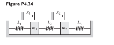
In Figure P4.24 when
Expert Solution & Answer
Want to see the full answer?
Check out a sample textbook solution
Students have asked these similar questions
Q1: The system shown has two masses. Beam of mass (Jo#m L²
kg.m²) rotates about fixed point (O) and its free end is connected to
disk rotates about fixed point (O₂). Consider all connecting links are
massless and rigid. Find
1- The displacements of points A, B, and C in addition to the
rotations of masses, all in terms of 0.
2- Find the equation of motion (EOM) in terms of 0.
3- What is the natural frequency of the system?
0
L/2
8
Energy methods
A
Jo=m L²2
L/2
Joz-m R²
R
C
B
C
128
For the following mechanical systems,
obtain the equations of motion in Laplace
domain.
A uniform rod of mass m is pivoted at a point O as shown in Figure 2. The rod is constrained by three
identical linear springs, and a point mass M is attached at the end of the rod (also shown in Figure 2).
The parameters of the system are as follows: L= 1 m, k = 1000 N/m, m= 50 kg, M = 25 kg.
i.
Derive the equation of motion of the system in terms of the angular displacement (0). Choose
O as the clockwise angular displacement of the rod from the system's static equilibrium
position.
Chapter 4 Solutions
System Dynamics
Ch. 4 - Prob. 4.1PCh. 4 - In the spring arrangement shown in Figure P4.2....Ch. 4 - In the arrangement shown in Figure P4.3, a cable...Ch. 4 - In the spring arrangement shown in Figure P4.4,...Ch. 4 - For the system shown in Figure P4.5, assume that...Ch. 4 - The two stepped solid cylinders in Figure P4.6...Ch. 4 - A table with four identical legs supports a...Ch. 4 - The beam shown in Figure P4.8 has been stiffened...Ch. 4 - Determine the equivalent spring constant of the...Ch. 4 - Compute the equivalent torsional spring constant...
Ch. 4 - Plot the spring force felt by the mass shown in...Ch. 4 - Calculate the expression for the natural frequency...Ch. 4 - Prob. 4.13PCh. 4 - Obtain the expression for the natural frequency of...Ch. 4 - 4.15 A connecting rod having a mass of 3.6 kg is...Ch. 4 - Calculate the expression for the natural frequency...Ch. 4 - For each of the systems shown in Figure P4.17, the...Ch. 4 - The mass m in Figure P4.18 is attached to a rigid...Ch. 4 - In the pulley system shown in Figure P4.19, the...Ch. 4 - Prob. 4.20PCh. 4 - Prob. 4.21PCh. 4 - Prob. 4.22PCh. 4 - In Figure P4.23, assume that the cylinder rolls...Ch. 4 - In Figure P4.24 when x1=x2=0 the springs are at...Ch. 4 - 4.25 In Figure P4.25 model the three shafts as...Ch. 4 - In Figure P4.26 when 1=2=0 the spring is at its...Ch. 4 - Prob. 4.27PCh. 4 - For the system shown in Figure P4.28, suppose that...Ch. 4 - For the system shown in Figure P4.29, suppose that...Ch. 4 - Prob. 4.30PCh. 4 - For Figure P4.31, the equilibrium position...Ch. 4 - Prob. 4.32PCh. 4 - Prob. 4.33PCh. 4 - 4.34 For Figure P4.34, assume that the cylinder...Ch. 4 - Use the Rayleigh method to obtain an expression...Ch. 4 - Prob. 4.36PCh. 4 - 4.37 Determine the natural frequency of the system...Ch. 4 - Determine the natural frequency of the system...Ch. 4 - Use Rayleigh's method to calculate the expression...Ch. 4 - Prob. 4.40PCh. 4 - Prob. 4.41PCh. 4 - Prob. 4.42PCh. 4 - The vibration of a motor mounted on the end of a...Ch. 4 - Prob. 4.44PCh. 4 - Prob. 4.45PCh. 4 - A certain cantilever beam vibrates at a frequency...Ch. 4 - Prob. 4.47PCh. 4 - 4.48 The static deflection of a cantilever beam is...Ch. 4 - Figure P4.49 shows a winch supported by a...Ch. 4 - Prob. 4.50PCh. 4 - Prob. 4.51PCh. 4 - Prob. 4.52PCh. 4 - 4.53 In Figure P4.53 a motor supplies a torque T...Ch. 4 - Derive the equation of motion for the lever system...Ch. 4 - Prob. 4.55PCh. 4 - Figure P4.56a shows a Houdaille damper, which is a...Ch. 4 - 4.57 Refer to Figure P4.57. Determine the...Ch. 4 - For the system shown in Figure P4.58, obtain the...Ch. 4 - Find the transfer function ZsXs for the system...Ch. 4 - Prob. 4.60PCh. 4 - Find the transfer function YsXs for the system...Ch. 4 - Prob. 4.62PCh. 4 - 4.63 In the system shown in Figure P4.63, the...Ch. 4 - Prob. 4.64PCh. 4 - Figure P4.65 shows a rack-and-pinion gear in which...Ch. 4 - Figure P4.66 shows a drive train with a spur-gear...Ch. 4 - Prob. 4.67PCh. 4 - Prob. 4.68PCh. 4 - Prob. 4.69PCh. 4 - Figure P4.70 shows a quarter-car model that...Ch. 4 - Prob. 4.71PCh. 4 - 4.72 Derive the equation of motion for the system...Ch. 4 - A boxcar moving at 1.3 m/s hits the shock absorber...Ch. 4 - For the systems shown in Figure P4.74, assume that...Ch. 4 - Refer to Figure P4.75a, which shows a ship’s...Ch. 4 - In this problem, we make all the same assumptions...Ch. 4 - Refer to Figure P4.79a, which shows a water tank...Ch. 4 - The “sky crane” shown on the text cover was a...Ch. 4 - Prob. 4.81PCh. 4 - Prob. 4.82PCh. 4 - Suppose a mass in moving with a speed 1 becomes...Ch. 4 - Consider the system shown in Figure 4.6.3. Suppose...Ch. 4 - Prob. 4.86PCh. 4 - Figure P4.87 shows a mass m with an attached...Ch. 4 - Figure P4.88 represents a drop forging process....Ch. 4 - Refer to Figure P4.89. A mass m drops from a...Ch. 4 - Prob. 4.90PCh. 4 - (a) Obtain the equations of motion of the system...Ch. 4 - Refer to part (a) of Problem 4.90. Use MATLAB to...Ch. 4 - Refer to Problem 4.91. Use MATLAB to obtain the...Ch. 4 - 4.94 (a) Obtain the equations of motion of the...Ch. 4 -
4.95 (a) Obtain the equations of motion of the...
Knowledge Booster


Learn more about
Need a deep-dive on the concept behind this application? Look no further. Learn more about this topic, mechanical-engineering and related others by exploring similar questions and additional content below.Similar questions
- Refer to Figure Q2. A tray of mass mı is supported by 3 springs as shown in Figure 3(a). The natural frequency fa is 5.0Hz. An additional mass motor of m2 = 3.0kg (in OFF condition) is placed at the center on top of the mass, the natural frequency is observed to be 2.5Hz. a) Calculate the mass mı. The motor m2 is ON and it rotates at the speed of 600 rpm. Calculate: a) The transmissibility b) Attenuation c) Explain what will happen if the system run at Resonant Frequency m2 m1 Figure 2(a): Original system Figure 2(b): system with m2 addedarrow_forward4.1. Some problems. 1. A spherical pendulum consists of a bob of mass m suspended from an inextensible string of length l. Determine the Lagrangian and the equations of motion. See Figure |1.7. Note that 0, the polar angle, is measured from the positive z axis, and p, the azimuthal angle, is measured from the x axis in the x – y plane.? Solution:arrow_forwardFor this problem, take a look at Figure 2 below. A disk with uniformly distributed mass m, radius R, and center of mass at point O is connected to a combination of springs at point P, which are then connected to a fixed wall. The disk rolls without slipping at point Q along an inclined plane that is at an angle a from the horizontal. Gravity acts in the vertical direction (towards the bottom of the page). ₁ is the linear coordinate of the point O along the inclined plane. The positive direction of ₁ is as shown. When the springs are undeflected, *₁ = 0. An angle , about the instant center of rotation, is shown. You may assume that the motion (and therefore angle ) is small. puny m Massless structure between springs R Figure 2: System schematic. Your tasks: A Draw the FBD for the disk. Don't forget the forces at point Q B Derive the equation of motion with as the dynamic variable. Be sure to put it in input-output standard form (inputs and constant forces on the right, things related to…arrow_forward
- For each of the systems shown in Figure P4.52, the input is the force f andthe outputs are the displacements x1 and x2 of the masses. The equilibriumpositions with f = 0 correspond to x1 = x2 = 0. Neglect any friction betweenthe masses and the surface. Derive the equations of motion of the systems.arrow_forwardFor the scotch yoke mechanism shown in the figure P4.1, the horizontal position of link 4 canbe described as x = 3 cos (50t + 40°). Determine the displacement of link 4 during theinterval of 3.8 to 4.7 s.arrow_forwardFor the system shown in Figure Q 4: ) Draw the free body diagram (1) Formulate the equation of motion using (a) Newton's second law (b) Principle of virtual work (c) Principle of conservation of energy k1 k2 Figure Q4arrow_forward
- find the equations of motion using the lagrange equations of motion. Point A and C are moving vertically, points D and B are moving horizontally. the unloaded spring has length equal to l*sqrt(2). Each rod has mass m amd length l, spring constant is equal to karrow_forwardP4.8 Determine the rotational speed of link 3 of the mechanism given in figure P4.8 for the position shown. Use a complex numbers approacharrow_forwardConsider the mass-spring system in Figure 1. For the system shown in Figure 1, suppose that k₁ = k, k₂ = k3 = 2k, and m₁ = m₂ = m. Obtain the equations of motion in terms of X₁ and x₂. Assume that x₂ > x₁. X1 A. Draw the necessary free-body diagrams and derive the differential equations of motion. B. Determine the transfer functions X₂ (s)/F(s). All the initial conditions are assumed to be zero. x2 k3 k₂ m1 m2 www f(t) Figure 1 k₁arrow_forward
- Question 4For the dynamic system shown in the figure,derive the equations of motion using Lagrange’s equations.arrow_forward4 = k = k k2 = 2k F X kz = 3k 1. Derive the expression for the equivalent spring constant that relates the applied force F to the resulting displacement x of the system shown in the figure above. Assume the displacement of the link to be small.arrow_forwardIn the system shown in Figure 1, assume that the rod pivoted at point P is massless and perfectly rigid. A mass m is attached to the other end of the rod and supported by a damper at distance L, and a spring at a distance L2 to the pivot point P. The displacement x of the mass is measured from the equilibrium position of the system. Assuming that x is small, obtain the equation of motion of the system by applying Newton's laws.arrow_forward
arrow_back_ios
SEE MORE QUESTIONS
arrow_forward_ios
Recommended textbooks for you
 Elements Of ElectromagneticsMechanical EngineeringISBN:9780190698614Author:Sadiku, Matthew N. O.Publisher:Oxford University Press
 Mechanics of Materials (10th Edition)Mechanical EngineeringISBN:9780134319650Author:Russell C. HibbelerPublisher:PEARSON
 Thermodynamics: An Engineering ApproachMechanical EngineeringISBN:9781259822674Author:Yunus A. Cengel Dr., Michael A. BolesPublisher:McGraw-Hill Education
 Control Systems EngineeringMechanical EngineeringISBN:9781118170519Author:Norman S. NisePublisher:WILEY
 Mechanics of Materials (MindTap Course List)Mechanical EngineeringISBN:9781337093347Author:Barry J. Goodno, James M. GerePublisher:Cengage Learning
 Engineering Mechanics: StaticsMechanical EngineeringISBN:9781118807330Author:James L. Meriam, L. G. Kraige, J. N. BoltonPublisher:WILEY
Elements Of Electromagnetics
Mechanical Engineering
ISBN:9780190698614
Author:Sadiku, Matthew N. O.
Publisher:Oxford University Press
Mechanics of Materials (10th Edition)
Mechanical Engineering
ISBN:9780134319650
Author:Russell C. Hibbeler
Publisher:PEARSON
Thermodynamics: An Engineering Approach
Mechanical Engineering
ISBN:9781259822674
Author:Yunus A. Cengel Dr., Michael A. Boles
Publisher:McGraw-Hill Education
Control Systems Engineering
Mechanical Engineering
ISBN:9781118170519
Author:Norman S. Nise
Publisher:WILEY
Mechanics of Materials (MindTap Course List)
Mechanical Engineering
ISBN:9781337093347
Author:Barry J. Goodno, James M. Gere
Publisher:Cengage Learning
Engineering Mechanics: Statics
Mechanical Engineering
ISBN:9781118807330
Author:James L. Meriam, L. G. Kraige, J. N. Bolton
Publisher:WILEY
Mechanical SPRING DESIGN Strategy and Restrictions in Under 15 Minutes!; Author: Less Boring Lectures;https://www.youtube.com/watch?v=dsWQrzfQt3s;License: Standard Youtube License