
System Dynamics
3rd Edition
ISBN: 9780073398068
Author: III William J. Palm
Publisher: MCG
expand_more
expand_more
format_list_bulleted
Videos
Textbook Question
Chapter 4, Problem 4.11P
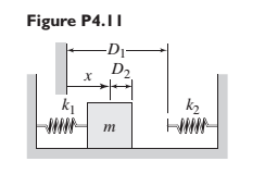
Plot the spring force felt by the mass shown in Figure P4.11 as a function of the displacement x. When x = 0. spring 1 is at its free length. Spring 2 is at its free length in the configuration shown.
Expert Solution & Answer
Want to see the full answer?
Check out a sample textbook solution
Students have asked these similar questions
Three springs with different spring
constants are connected as shown below.
You are going to use spring elements to
simulate this system. Suppose that the
spring constants of the first, second and
third elements are k1=3,410 N/m,
k2=3,160 N/m and k3=3,380 N/m,
respectively. Two horizontal forces are
applied to the system (as shown) at nodes.
2 and 3. Find the displacement of node 3
and write your answer in mm (millimetre).
Hint: Write your answer with 5 decimal
places. For example if you calculated the
value 1.2345678, then rounding off to 5
decimal places yields 1.23457 and that is
the value you need to type in the answer
box.
U₁=0
(1)
F₂ = 2N
U₂ = ?
F3 = -1N
(2)
M
U3 = ?
(3)
U4 = 0
For the scotch yoke mechanism shown in the figure P4.1, the horizontal position of link 4 canbe described as x = 3 cos (50t + 40°). Determine the displacement of link 4 during theinterval of 3.8 to 4.7 s.
Q1: The system shown has two masses. Beam of mass (Jo#m L²
kg.m²) rotates about fixed point (O) and its free end is connected to
disk rotates about fixed point (O₂). Consider all connecting links are
massless and rigid. Find
1- The displacements of points A, B, and C in addition to the
rotations of masses, all in terms of 0.
2- Find the equation of motion (EOM) in terms of 0.
3- What is the natural frequency of the system?
0
L/2
8
Energy methods
A
Jo=m L²2
L/2
Joz-m R²
R
C
B
C
128
Chapter 4 Solutions
System Dynamics
Ch. 4 - Prob. 4.1PCh. 4 - In the spring arrangement shown in Figure P4.2....Ch. 4 - In the arrangement shown in Figure P4.3, a cable...Ch. 4 - In the spring arrangement shown in Figure P4.4,...Ch. 4 - For the system shown in Figure P4.5, assume that...Ch. 4 - The two stepped solid cylinders in Figure P4.6...Ch. 4 - A table with four identical legs supports a...Ch. 4 - The beam shown in Figure P4.8 has been stiffened...Ch. 4 - Determine the equivalent spring constant of the...Ch. 4 - Compute the equivalent torsional spring constant...
Ch. 4 - Plot the spring force felt by the mass shown in...Ch. 4 - Calculate the expression for the natural frequency...Ch. 4 - Prob. 4.13PCh. 4 - Obtain the expression for the natural frequency of...Ch. 4 - 4.15 A connecting rod having a mass of 3.6 kg is...Ch. 4 - Calculate the expression for the natural frequency...Ch. 4 - For each of the systems shown in Figure P4.17, the...Ch. 4 - The mass m in Figure P4.18 is attached to a rigid...Ch. 4 - In the pulley system shown in Figure P4.19, the...Ch. 4 - Prob. 4.20PCh. 4 - Prob. 4.21PCh. 4 - Prob. 4.22PCh. 4 - In Figure P4.23, assume that the cylinder rolls...Ch. 4 - In Figure P4.24 when x1=x2=0 the springs are at...Ch. 4 - 4.25 In Figure P4.25 model the three shafts as...Ch. 4 - In Figure P4.26 when 1=2=0 the spring is at its...Ch. 4 - Prob. 4.27PCh. 4 - For the system shown in Figure P4.28, suppose that...Ch. 4 - For the system shown in Figure P4.29, suppose that...Ch. 4 - Prob. 4.30PCh. 4 - For Figure P4.31, the equilibrium position...Ch. 4 - Prob. 4.32PCh. 4 - Prob. 4.33PCh. 4 - 4.34 For Figure P4.34, assume that the cylinder...Ch. 4 - Use the Rayleigh method to obtain an expression...Ch. 4 - Prob. 4.36PCh. 4 - 4.37 Determine the natural frequency of the system...Ch. 4 - Determine the natural frequency of the system...Ch. 4 - Use Rayleigh's method to calculate the expression...Ch. 4 - Prob. 4.40PCh. 4 - Prob. 4.41PCh. 4 - Prob. 4.42PCh. 4 - The vibration of a motor mounted on the end of a...Ch. 4 - Prob. 4.44PCh. 4 - Prob. 4.45PCh. 4 - A certain cantilever beam vibrates at a frequency...Ch. 4 - Prob. 4.47PCh. 4 - 4.48 The static deflection of a cantilever beam is...Ch. 4 - Figure P4.49 shows a winch supported by a...Ch. 4 - Prob. 4.50PCh. 4 - Prob. 4.51PCh. 4 - Prob. 4.52PCh. 4 - 4.53 In Figure P4.53 a motor supplies a torque T...Ch. 4 - Derive the equation of motion for the lever system...Ch. 4 - Prob. 4.55PCh. 4 - Figure P4.56a shows a Houdaille damper, which is a...Ch. 4 - 4.57 Refer to Figure P4.57. Determine the...Ch. 4 - For the system shown in Figure P4.58, obtain the...Ch. 4 - Find the transfer function ZsXs for the system...Ch. 4 - Prob. 4.60PCh. 4 - Find the transfer function YsXs for the system...Ch. 4 - Prob. 4.62PCh. 4 - 4.63 In the system shown in Figure P4.63, the...Ch. 4 - Prob. 4.64PCh. 4 - Figure P4.65 shows a rack-and-pinion gear in which...Ch. 4 - Figure P4.66 shows a drive train with a spur-gear...Ch. 4 - Prob. 4.67PCh. 4 - Prob. 4.68PCh. 4 - Prob. 4.69PCh. 4 - Figure P4.70 shows a quarter-car model that...Ch. 4 - Prob. 4.71PCh. 4 - 4.72 Derive the equation of motion for the system...Ch. 4 - A boxcar moving at 1.3 m/s hits the shock absorber...Ch. 4 - For the systems shown in Figure P4.74, assume that...Ch. 4 - Refer to Figure P4.75a, which shows a ship’s...Ch. 4 - In this problem, we make all the same assumptions...Ch. 4 - Refer to Figure P4.79a, which shows a water tank...Ch. 4 - The “sky crane” shown on the text cover was a...Ch. 4 - Prob. 4.81PCh. 4 - Prob. 4.82PCh. 4 - Suppose a mass in moving with a speed 1 becomes...Ch. 4 - Consider the system shown in Figure 4.6.3. Suppose...Ch. 4 - Prob. 4.86PCh. 4 - Figure P4.87 shows a mass m with an attached...Ch. 4 - Figure P4.88 represents a drop forging process....Ch. 4 - Refer to Figure P4.89. A mass m drops from a...Ch. 4 - Prob. 4.90PCh. 4 - (a) Obtain the equations of motion of the system...Ch. 4 - Refer to part (a) of Problem 4.90. Use MATLAB to...Ch. 4 - Refer to Problem 4.91. Use MATLAB to obtain the...Ch. 4 - 4.94 (a) Obtain the equations of motion of the...Ch. 4 -
4.95 (a) Obtain the equations of motion of the...
Knowledge Booster


Learn more about
Need a deep-dive on the concept behind this application? Look no further. Learn more about this topic, mechanical-engineering and related others by exploring similar questions and additional content below.Similar questions
- A mass weighing 4 pounds is attached to a spring whose spring constant is 36 lb/ft. Find the equation of motion.arrow_forwardRefer to Figure Q2. A tray of mass mı is supported by 3 springs as shown in Figure 3(a). The natural frequency fa is 5.0Hz. An additional mass motor of m2 = 3.0kg (in OFF condition) is placed at the center on top of the mass, the natural frequency is observed to be 2.5Hz. a) Calculate the mass mı. The motor m2 is ON and it rotates at the speed of 600 rpm. Calculate: a) The transmissibility b) Attenuation c) Explain what will happen if the system run at Resonant Frequency m2 m1 Figure 2(a): Original system Figure 2(b): system with m2 addedarrow_forward3.19 The geared system shown in Figure P3.19 represents an elevator system. The motor has an inertia I, and supplies a torque T₁. Neglect the inertias of the gears, and assume that the cable does not slip on the pulley. Derive an expression for the equivalent inertia I felt on the input shaft (shaft 1). Then derive the dynamic model of the system in terms of the speed oo, and the applied torque T₁. The pulley radius is R.arrow_forward
- Two carts with negligible rolling friction are connected as shown in Figure (1b). An input force u(t) is applied. The masses of the two carts are M, and M, and their displacements are x(t) and q(t), respectively. The carts are connected by a spring k and a damper b. Answer the following questions: (b) By using Newton's Second Law, derive two mathematical equations that describe the motion of the two carts. Hence derive the following two transfer functions: G,(s) = S) U(s) (c) x(1) 9(t) k M, M2 u(t) Figure (1b)arrow_forward6. The electro-mechanical system shown below consists of an electric motor with input voltage V which drives inertia I in the mechanical system (see torque T). Find the governing differential equations of motion for this electro-mechanical system in terms of the input voltage to the motor and output displacement y. Electrical System puthiy C V V₁ R bac (0) T bac T Motor - Motor Input Voltage - Motor Back EMF = Kbac ( - Motor Angular Velocity - Motor Output Torque = K₂ i Kbacs K₁ - Motor Constants Mechanical System M T Frictionless Supportarrow_forward2. Find the k equivalent of the system, if each spring has a spring constant of 20 lb/in except for the only spring on the bottom which has a spring constantant of 50 lb/in.arrow_forward
- 2. Duffing's equation is a model for a dynamic system that includes a damping term and a nonlinear stiffness term. It most notably describes dynamics of electrical systems, but it has a simple analog as a nonlinear vibrations problem. Derive the non-homogeneous Duffings equation below using Hamilton's Principle. Start from the definition of the kinetic energy of a unit mass, and the virtual work of the springs and damper. Note, the spring force terms are both derivable from an energy function. x+cx+kx+vx³ = F sin sin(at)arrow_forwardQ4/ For the figure below the spring is used to stop a 10 kg package. If the maximum deflection in the spring is 70 mm, (a) the total work of the system in the figure below is: 8m/s H=0,25 /K=400N/m 10kg 500m 0-30 (b): The total work when theta =0 equal to: *arrow_forwardFor the following mechanical systems, obtain the equations of motion in Laplace domain.arrow_forward
- BC = 3 in BD = 2 in 1 2 in 0=30° B FIGURE P3.3arrow_forwardP4.8 Determine the rotational speed of link 3 of the mechanism given in figure P4.8 for the position shown. Use a complex numbers approacharrow_forwardAnswer the following problem and write your complete solution and graph. 1. Write the equation of motion for the system given in the figure for the case that F(t) = F cos wt and the surface is friction free. Does the angle affect the magnitude of oscillation? Diagram: wwwm mass F(0) Fig. 4.4 Mass tied on the spring and Dashpotarrow_forward
arrow_back_ios
SEE MORE QUESTIONS
arrow_forward_ios
Recommended textbooks for you
 Elements Of ElectromagneticsMechanical EngineeringISBN:9780190698614Author:Sadiku, Matthew N. O.Publisher:Oxford University Press
 Mechanics of Materials (10th Edition)Mechanical EngineeringISBN:9780134319650Author:Russell C. HibbelerPublisher:PEARSON
 Thermodynamics: An Engineering ApproachMechanical EngineeringISBN:9781259822674Author:Yunus A. Cengel Dr., Michael A. BolesPublisher:McGraw-Hill Education
 Control Systems EngineeringMechanical EngineeringISBN:9781118170519Author:Norman S. NisePublisher:WILEY
 Mechanics of Materials (MindTap Course List)Mechanical EngineeringISBN:9781337093347Author:Barry J. Goodno, James M. GerePublisher:Cengage Learning
 Engineering Mechanics: StaticsMechanical EngineeringISBN:9781118807330Author:James L. Meriam, L. G. Kraige, J. N. BoltonPublisher:WILEY
Elements Of Electromagnetics
Mechanical Engineering
ISBN:9780190698614
Author:Sadiku, Matthew N. O.
Publisher:Oxford University Press
Mechanics of Materials (10th Edition)
Mechanical Engineering
ISBN:9780134319650
Author:Russell C. Hibbeler
Publisher:PEARSON
Thermodynamics: An Engineering Approach
Mechanical Engineering
ISBN:9781259822674
Author:Yunus A. Cengel Dr., Michael A. Boles
Publisher:McGraw-Hill Education
Control Systems Engineering
Mechanical Engineering
ISBN:9781118170519
Author:Norman S. Nise
Publisher:WILEY
Mechanics of Materials (MindTap Course List)
Mechanical Engineering
ISBN:9781337093347
Author:Barry J. Goodno, James M. Gere
Publisher:Cengage Learning
Engineering Mechanics: Statics
Mechanical Engineering
ISBN:9781118807330
Author:James L. Meriam, L. G. Kraige, J. N. Bolton
Publisher:WILEY
How to balance a see saw using moments example problem; Author: Engineer4Free;https://www.youtube.com/watch?v=d7tX37j-iHU;License: Standard Youtube License