
Loose Leaf for Engineering Circuit Analysis Format: Loose-leaf
9th Edition
ISBN: 9781259989452
Author: Hayt
Publisher: Mcgraw Hill Publishers
expand_more
expand_more
format_list_bulleted
Concept explainers
Videos
Textbook Question
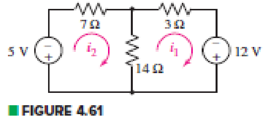
Chapter 4, Problem 33E
Obtain numerical values for the two mesh currents i1 and i2 in the circuit shown in Fig. 4.61.
Expert Solution & Answer
Want to see the full answer?
Check out a sample textbook solution
Students have asked these similar questions
4. Again assume each channel of our power supply can provide 30 V and we want to run a
60 V hair dryer motor. So, we again put the two channels in series for double the voltage.
But, if you try this with a non-isolated supply, bad things will happen. Don't do that. The
following depicts a circuit where internally the supplies have a common ground (i.e., they
are not isolated).
Non-Isolated Power Supply
Droop2
ww
1mQ
Channel2
30V
3.3A max
Channel1
30V
3.3A max
Droop1
1mQ
I
I
I
1
I
Red
1
I
1
Black
Red
Black
JumperCable
26mQ
15A max
Motor
1200
Needs -60V
(a) Show that the current through the jumper cable will greatly exceed its current rating
(which, as shown in the schematic, is 15 A). If this happens for more than a very short
time, it will melt.
(b) Show that the current through Channell greatly exceeds its maximum current rating.
If the short circuit protection circuitry doesnt activate quickly, you will fry your power
supply.
Hint: You can redraw the circuit in a manner similar to…
Q4) Determine the maximum power delivered to the variable resistor R.
3V,
592
ww
1592
592
ww
692
ww
Vx
www
Answers to input:
What is the Thevenin equivalent voltage for the circuit from the perspective of R (ie for the
circuit excluding R)?
What is the Thevenin equivalent resistance for the circuit from the perspective of R (ie for the
circuit excluding R)?
What is the maximum power that can be delivered to R in mW?
The resistance of each brake light bulb on an automobile is 4.9 . Use the fact that cars have 12-V electrical systems to compute the current that flows in each bulb if they are connected in series. ( for simplicity, assume that the circuit is only composed of one brake light bulb and the car battery)
A
Chapter 4 Solutions
Loose Leaf for Engineering Circuit Analysis Format: Loose-leaf
Ch. 4.1 - For the circuit of Fig. 4.3, determine the nodal...Ch. 4.1 - For the circuit of Fig. 4.5, compute the voltage...Ch. 4.1 - For the circuit of Fig. 4.8, determine the nodal...Ch. 4.2 - For the circuit of Fig. 4.11, compute the voltage...Ch. 4.3 - Determine i1 and i2 in the circuit in Fig. 4.19....Ch. 4.3 - Determine i1 and i2 in the circuit of Fig 4.21....Ch. 4.3 - Determine i1 in the circuit of Fig. 4.24 if the...Ch. 4.4 - Determine the current i1 in the circuit of Fig....Ch. 4.4 - Determine v3 in the circuit of Fig. 4.28. FIGURE...Ch. 4 - Solve the following systems of equations: (a) 2v2 ...
Ch. 4 - (a) Solve the following system of equations:...Ch. 4 - (a) Solve the following system of equations:...Ch. 4 - Correct (and verify by running) the following...Ch. 4 - In the circuit of Fig. 4.35, determine the current...Ch. 4 - Calculate the power dissipated in the 1 resistor...Ch. 4 - For the circuit in Fig. 4.37, determine the value...Ch. 4 - With the assistance of nodal analysis, determine...Ch. 4 - Prob. 9ECh. 4 - For the circuit of Fig. 4.40, determine the value...Ch. 4 - Use nodal analysis to find vP in the circuit shown...Ch. 4 - Prob. 12ECh. 4 - Prob. 13ECh. 4 - Determine a numerical value for each nodal voltage...Ch. 4 - Prob. 15ECh. 4 - Using nodal analysis as appropriate, determine the...Ch. 4 - Prob. 17ECh. 4 - Determine the nodal voltages as labeled in Fig....Ch. 4 - Prob. 19ECh. 4 - Prob. 20ECh. 4 - Employing supernode/nodal analysis techniques as...Ch. 4 - Prob. 22ECh. 4 - Prob. 23ECh. 4 - Prob. 24ECh. 4 - Repeat Exercise 23 for the case where the 12 V...Ch. 4 - Prob. 26ECh. 4 - Prob. 27ECh. 4 - Determine the value of k that will result in vx...Ch. 4 - Prob. 29ECh. 4 - Prob. 30ECh. 4 - Prob. 31ECh. 4 - Determine the currents flowing out of the positive...Ch. 4 - Obtain numerical values for the two mesh currents...Ch. 4 - Use mesh analysis as appropriate to determine the...Ch. 4 - Prob. 35ECh. 4 - Prob. 36ECh. 4 - Find the unknown voltage vx in the circuit in Fig....Ch. 4 - Prob. 38ECh. 4 - Prob. 39ECh. 4 - Determine the power dissipated in the 4 resistor...Ch. 4 - (a) Employ mesh analysis to determine the power...Ch. 4 - Define three clockwise mesh currents for the...Ch. 4 - Prob. 43ECh. 4 - Prob. 44ECh. 4 - Prob. 45ECh. 4 - Prob. 46ECh. 4 - Prob. 47ECh. 4 - Prob. 48ECh. 4 - Prob. 49ECh. 4 - Prob. 50ECh. 4 - Prob. 51ECh. 4 - Prob. 52ECh. 4 - For the circuit represented schematically in Fig....Ch. 4 - The circuit of Fig. 4.80 is modified such that the...Ch. 4 - The circuit of Fig. 4.81 contains three sources....Ch. 4 - Solve for the voltage vx as labeled in the circuit...Ch. 4 - Consider the five-source circuit of Fig. 4.83....Ch. 4 - Replace the dependent voltage source in the...Ch. 4 - After studying the circuit of Fig. 4.84, determine...Ch. 4 - Prob. 60ECh. 4 - Employ LTspice (or similar CAD tool) to verify the...Ch. 4 - Employ LTspice (or similar CAD tool) to verify the...Ch. 4 - Employ LTspice (or similar CAD tool) to verify the...Ch. 4 - Verify numerical values for each nodal voltage in...Ch. 4 - Prob. 65ECh. 4 - Prob. 66ECh. 4 - Prob. 67ECh. 4 - Prob. 68ECh. 4 - Prob. 69ECh. 4 - (a) Under what circumstances does the presence of...Ch. 4 - Referring to Fig. 4.88, (a) determine whether...Ch. 4 - Consider the LED circuit containing a red, green,...Ch. 4 - The LED circuit in Fig. 4.89 is used to mix colors...Ch. 4 - A light-sensing circuit is in Fig. 4.90, including...Ch. 4 - Use SPICE to analyze the circuit in Exercise 74 by...
Knowledge Booster


Learn more about
Need a deep-dive on the concept behind this application? Look no further. Learn more about this topic, electrical-engineering and related others by exploring similar questions and additional content below.Similar questions
- Part II. Kirchhoff's Laws in 3 loops. a. Find the necessary KVL/KCL equations to solve the problem. b. Compute for 11, 12, and 13 c. Resketch the circuit and label the current with the correct direction and values for each resistor. d. Find V₂,V4,V6, and V8 e. Find P2, P4P6,and Ps Hint: Look for the expression of the current at resistor 1 and resistor 2 before you proceed to the computation. R₁ R₂ m m 1₁ 12 R3 13 R₂ Given: R₁ = 102 R₂ = 200 R3 = 30.0 R₁ = 400 R5 = 15.2 R6 = 450 R7 = 250 Rε = 350 &1 R5 E₁ = 50V &₂ = 25V E3 = 15V m R8 E3 E2 R6 marrow_forward4.70 An automobile battery, when connected to a car radio, provides 12.5 V to the radio. When connected to a set of headlights, it provides 11.7 V to the head- lights. Assume the radio can be modeled as a 6.25 N resistor and the headlights can be modeled as a 0.65 N resistor. What are the Thévenin and Norton equivalents for the battery?arrow_forward"NORTON'S THEOREM" Please Find the Vo Using NORTONS’S THEOREM thankyou very much! I've included a cicruit app to check if your answer was correct and close to the value of currents and voltages which is 0.5V thankyou! I've been testing simple circuits to practice problems using different theorems,I appreciate you very much Thankyou!arrow_forward
- Q4: Find the Thevenin and Norton equivalent circuits for the circuit shown in Fig. 4 ww 60/ 25 V Figure 4arrow_forwardQ4) By using Nodal analysis, find all voltages and currents. 4 k2 VA 1 k2 4 mA Vc 14 10 V 2 k2 4 k2arrow_forwardPart II. Kirchhoff's Laws in 3 loops. a. Find the necessary KVL/KCL equations to solve the problem. b. Compute for 1₁, 12, and 13 c. Resketch the circuit and label the current with the correct direction and values for each resistor. d. Find V₂,V4V6,and V8 e. Find P2,P4,P6, and Ps Hint: Look for the expression of the current at resistor 1 and resistor 2 before you proceed to the computation. R₁ R2 m 1₁ R3 R4 E1 R₂ Given: R₁ = 100 R₂ = 200 R₂ = 300 R4 = 402 R5 15Ω R6 = 450 R7 = 250 R8 = 350 R5 &1 = 50V &2 = 25V &3 = 15V 13 12 m R8 E3 E2 m R6arrow_forward
- D LMH_chapter2-part2-homework. X + O File | C:/Users/DELL/Downloads/LMH_chapter2-part2-homework.pdf D Page view A Read aloud V Draw E Highlight O Erase 3 of 15 HW2 Use superposition to solve for v in the circuit of Fig. 4.87. 2Ω 6 A 4 A 8Ω 4ix 11:00 PM O Type here to search A a O 4) E ENG 3/22/2021arrow_forwardUse KCL to find the branch currents I1, h, Is, and I4. 44 64 2.4 54arrow_forwardChapter Assessments I Series-Parallel Circuit Analysis A. Solve for the required values with complete solution and progressive simplified circuits. Box the final answer for the required values. 1. In Fig. 4.19, solve for Ry, Ir, l2, I4, and P R, = 75 0 R= 150 2 V,- 12 V R-330 0 R- 180 1 Figure 4.19 2. For each of the circuits shown in Fig. 4.20, a. find the equivalent resistance seen by the source, b. find the power developed by the source. 210 0 280 N 100 120Ω180Ω: १15 0 90 V/ 40 Ω 30 mA ( 200 2 25 0 (a) (b) Figure 4.20 3. For the network in Fig. 4.21 Note: E is also equivalent to the designation Vs or Vr for voltage source and Is is equivalent to lr for total current of the circuit being analyzed. a. Find currents Is, I2, and 16. b. Find voltages V1 and Vs. c. Find the power delivered to the 3 ka resistor.arrow_forward
- 2Px 10 A Find the Norton equivalent circuit of the circuit in Fig. 4.45 at terminals a-b. wwarrow_forwardA)For the circuit shown in Figure 4, find the value of R, to maintain the load voltage (voltage across 4.7 K resistor) at 12.7 V with a load current (current through 4.7 KQ resistor) variation from 0 mA to 160 mA. Also, find Pzmax . Rs 4.7ΚΩ 20 V-arrow_forwardQ5 Draw the output voltage waveform for each circuit in Fig. 4.30 with respect the input. Show voltage levels. +1 V +1 V 0- -I V +2 V Vunmuy = 18 V Vrtmna = 110 V %3D -2 V (a) (b)arrow_forward
arrow_back_ios
SEE MORE QUESTIONS
arrow_forward_ios
Recommended textbooks for you
 Introductory Circuit Analysis (13th Edition)Electrical EngineeringISBN:9780133923605Author:Robert L. BoylestadPublisher:PEARSON
 Delmar's Standard Textbook Of ElectricityElectrical EngineeringISBN:9781337900348Author:Stephen L. HermanPublisher:Cengage Learning
 Programmable Logic ControllersElectrical EngineeringISBN:9780073373843Author:Frank D. PetruzellaPublisher:McGraw-Hill Education
 Fundamentals of Electric CircuitsElectrical EngineeringISBN:9780078028229Author:Charles K Alexander, Matthew SadikuPublisher:McGraw-Hill Education
 Electric Circuits. (11th Edition)Electrical EngineeringISBN:9780134746968Author:James W. Nilsson, Susan RiedelPublisher:PEARSON
 Engineering ElectromagneticsElectrical EngineeringISBN:9780078028151Author:Hayt, William H. (william Hart), Jr, BUCK, John A.Publisher:Mcgraw-hill Education,
Introductory Circuit Analysis (13th Edition)
Electrical Engineering
ISBN:9780133923605
Author:Robert L. Boylestad
Publisher:PEARSON
Delmar's Standard Textbook Of Electricity
Electrical Engineering
ISBN:9781337900348
Author:Stephen L. Herman
Publisher:Cengage Learning
Programmable Logic Controllers
Electrical Engineering
ISBN:9780073373843
Author:Frank D. Petruzella
Publisher:McGraw-Hill Education
Fundamentals of Electric Circuits
Electrical Engineering
ISBN:9780078028229
Author:Charles K Alexander, Matthew Sadiku
Publisher:McGraw-Hill Education
Electric Circuits. (11th Edition)
Electrical Engineering
ISBN:9780134746968
Author:James W. Nilsson, Susan Riedel
Publisher:PEARSON
Engineering Electromagnetics
Electrical Engineering
ISBN:9780078028151
Author:Hayt, William H. (william Hart), Jr, BUCK, John A.
Publisher:Mcgraw-hill Education,
Norton's Theorem and Thevenin's Theorem - Electrical Circuit Analysis; Author: The Organic Chemistry Tutor;https://www.youtube.com/watch?v=-kkvqr1wSwA;License: Standard Youtube License