
Loose Leaf for Engineering Circuit Analysis Format: Loose-leaf
9th Edition
ISBN: 9781259989452
Author: Hayt
Publisher: Mcgraw Hill Publishers
expand_more
expand_more
format_list_bulleted
Concept explainers
Videos
Textbook Question
Chapter 4.4, Problem 10P
Determine v3 in the circuit of Fig. 4.28.
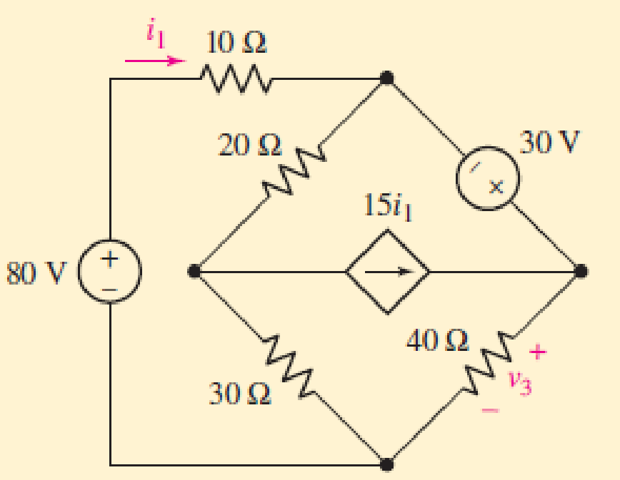
FIGURE 4.28
Expert Solution & Answer
Want to see the full answer?
Check out a sample textbook solution
Students have asked these similar questions
4.1.Part A: Ohm's law
This part aims at checking and proving Ohm's law. Using the fixed 5 V output from the power supply,
the 1k, 2k2 and 5k resistors, and considering all the possible unique circuit combinations with
these 3 resistors only, conduct the followings:
1. Before the lab session and manually
a) design and manually sketch your various circuits using the fixed 5 V power supply (i.e. put
the resistors in various parallel or series combinations),
b) calculate the current (immediately after the power supply) for all your circuits and find the
current and the power dissipated in each of the 3 resistors,
c) rank the circuits from maximum to minimum current observed immediately after the power
supply, and
d) prepare your report and have it with you electronically at the time of your lab session.
2. Before the lab session, and using the LushProjects simulator (see above URL)
a) make simulation files and simulate all your circuits,
b) check and compare the results with the manual…
4.80 Find the Thévenin equivalent with respect to the
terminals a,b in the circuit in Fig. P4.80.
Figure P4.80
20 0
24 N
10 0
100
50 0
13i
Find the Thévenin equivalent with respect to the
terminals a,b for the circuit in Fig. P4.67.
Figure P4.67
10 A
30 0
5.2 0
w-
a
500 V
12 0
b
Chapter 4 Solutions
Loose Leaf for Engineering Circuit Analysis Format: Loose-leaf
Ch. 4.1 - For the circuit of Fig. 4.3, determine the nodal...Ch. 4.1 - For the circuit of Fig. 4.5, compute the voltage...Ch. 4.1 - For the circuit of Fig. 4.8, determine the nodal...Ch. 4.2 - For the circuit of Fig. 4.11, compute the voltage...Ch. 4.3 - Determine i1 and i2 in the circuit in Fig. 4.19....Ch. 4.3 - Determine i1 and i2 in the circuit of Fig 4.21....Ch. 4.3 - Determine i1 in the circuit of Fig. 4.24 if the...Ch. 4.4 - Determine the current i1 in the circuit of Fig....Ch. 4.4 - Determine v3 in the circuit of Fig. 4.28. FIGURE...Ch. 4 - Solve the following systems of equations: (a) 2v2 ...
Ch. 4 - (a) Solve the following system of equations:...Ch. 4 - (a) Solve the following system of equations:...Ch. 4 - Correct (and verify by running) the following...Ch. 4 - In the circuit of Fig. 4.35, determine the current...Ch. 4 - Calculate the power dissipated in the 1 resistor...Ch. 4 - For the circuit in Fig. 4.37, determine the value...Ch. 4 - With the assistance of nodal analysis, determine...Ch. 4 - Prob. 9ECh. 4 - For the circuit of Fig. 4.40, determine the value...Ch. 4 - Use nodal analysis to find vP in the circuit shown...Ch. 4 - Prob. 12ECh. 4 - Prob. 13ECh. 4 - Determine a numerical value for each nodal voltage...Ch. 4 - Prob. 15ECh. 4 - Using nodal analysis as appropriate, determine the...Ch. 4 - Prob. 17ECh. 4 - Determine the nodal voltages as labeled in Fig....Ch. 4 - Prob. 19ECh. 4 - Prob. 20ECh. 4 - Employing supernode/nodal analysis techniques as...Ch. 4 - Prob. 22ECh. 4 - Prob. 23ECh. 4 - Prob. 24ECh. 4 - Repeat Exercise 23 for the case where the 12 V...Ch. 4 - Prob. 26ECh. 4 - Prob. 27ECh. 4 - Determine the value of k that will result in vx...Ch. 4 - Prob. 29ECh. 4 - Prob. 30ECh. 4 - Prob. 31ECh. 4 - Determine the currents flowing out of the positive...Ch. 4 - Obtain numerical values for the two mesh currents...Ch. 4 - Use mesh analysis as appropriate to determine the...Ch. 4 - Prob. 35ECh. 4 - Prob. 36ECh. 4 - Find the unknown voltage vx in the circuit in Fig....Ch. 4 - Prob. 38ECh. 4 - Prob. 39ECh. 4 - Determine the power dissipated in the 4 resistor...Ch. 4 - (a) Employ mesh analysis to determine the power...Ch. 4 - Define three clockwise mesh currents for the...Ch. 4 - Prob. 43ECh. 4 - Prob. 44ECh. 4 - Prob. 45ECh. 4 - Prob. 46ECh. 4 - Prob. 47ECh. 4 - Prob. 48ECh. 4 - Prob. 49ECh. 4 - Prob. 50ECh. 4 - Prob. 51ECh. 4 - Prob. 52ECh. 4 - For the circuit represented schematically in Fig....Ch. 4 - The circuit of Fig. 4.80 is modified such that the...Ch. 4 - The circuit of Fig. 4.81 contains three sources....Ch. 4 - Solve for the voltage vx as labeled in the circuit...Ch. 4 - Consider the five-source circuit of Fig. 4.83....Ch. 4 - Replace the dependent voltage source in the...Ch. 4 - After studying the circuit of Fig. 4.84, determine...Ch. 4 - Prob. 60ECh. 4 - Employ LTspice (or similar CAD tool) to verify the...Ch. 4 - Employ LTspice (or similar CAD tool) to verify the...Ch. 4 - Employ LTspice (or similar CAD tool) to verify the...Ch. 4 - Verify numerical values for each nodal voltage in...Ch. 4 - Prob. 65ECh. 4 - Prob. 66ECh. 4 - Prob. 67ECh. 4 - Prob. 68ECh. 4 - Prob. 69ECh. 4 - (a) Under what circumstances does the presence of...Ch. 4 - Referring to Fig. 4.88, (a) determine whether...Ch. 4 - Consider the LED circuit containing a red, green,...Ch. 4 - The LED circuit in Fig. 4.89 is used to mix colors...Ch. 4 - A light-sensing circuit is in Fig. 4.90, including...Ch. 4 - Use SPICE to analyze the circuit in Exercise 74 by...
Knowledge Booster


Learn more about
Need a deep-dive on the concept behind this application? Look no further. Learn more about this topic, electrical-engineering and related others by exploring similar questions and additional content below.Similar questions
- An attenuator is an interface circuit that reduces the voltage level without changing the output resistance. (a) By specifying R, and R, of the interface circuit in Fig. 4.150, design an attenuator that will meet the following requirements: V. 0.125, Vg Rea = RTh = Rg = 100 N (b) Using the interface designed in part (a), calculate the current through a load of R1 = 50 N when V = 12 V. R, Rp RL Load Attenuator Reg In part (a) determine the values of Rs and RP. ww wwwarrow_forward4.94 Use superposition to solve for i, and v, in the cir- cuit in Fig. P4.94. Figure P4.94 45 0 2 A 60 N 50 ww 10 V V, 20 2 310 0arrow_forwardQ4/ A) For the circuit shown below, calculate the current i, the conductance G, and the power P. 30 V (+ 5 k2arrow_forward
- 4.21 Use the node-voltage method to find v▲ in the circuit in Fig. P4.21. 100 V FIGURE P4.21 ww 10 (2 www 80 0 ww AVA + 60 0 20 Ω V 300arrow_forward4.70 An automobile battery, when connected to a car radio, provides 12.5 V to the radio. When connected to a set of headlights, it provides 11.7 V to the head- lights. Assume the radio can be modeled as a 6.25 N resistor and the headlights can be modeled as a 0.65 N resistor. What are the Thévenin and Norton equivalents for the battery?arrow_forward4.67 PSPICE MULTISIM Find the Thévenin equivalent with respect to the terminals a, b for the circuit in Fig. P4.679. Figure P4.67 300 V + 40 Ω 3A 150 Ω 10 Ω Σ8Ω aarrow_forward
- Example 4.7 Find v, in Fig. 4.20 using source transformation. Solution: The circuit in Fig. 4.20 involves a voltage-controlled dependent current source. We transform this dependent current source as well as the 6-V 0.25v independent voltage source as shown in Fig. 4.21(a). The 18-V voltage source is not transformed because it is not connected in series with any resistor. The two 2-N resistors in parallel combine to give a 1-N resistor, which is in parallel with the 3-A current source. The current source is transformed to a voltage source as shown in Fig. 4.21(b). Notice that the terminals for Uy are intact. Applying KVL around the loop in Fig. 4.21(b) gives 6 V 18 V Figure 4.20 For Example 4.7. -3 + 5i + vx + 18 = 0 (4.7.1)arrow_forwardQ4(4*2)/A/ For the network of the figure shown below, using the maximum power transfer method to :the resistor (R) and find the following 10 V 22 ww 32 R 20 V 52 O 6 Aarrow_forward4.8 Use the node-voltage method to find the total power dissipated in the circuit in Fig. P4.8. 120 V FIGURE P4.8 60 www 1250 4 A 100 200 ( www 200 1 Aarrow_forward
- Practice (4.10): If vi = 5 V and vz = 5 V, find va in the op amp circuit of Fig. 4.31. Ans: 35 V. 60 ka 20 ka ww- Vo 50 k2 30 k2 10 k2 Fig. 4.31 wwarrow_forwardQ4: Find the Thevenin and Norton equivalent circuits for the circuit shown in Fig. 4 ww 60/ 25 V Figure 4arrow_forward#4. What is v(t) in the circuit of Fig. 4? 120 cos (2004) + 452 BUF Fig4 ✰✰✰✰✰ FIVE STA T 310m Harrow_forward
arrow_back_ios
SEE MORE QUESTIONS
arrow_forward_ios
Recommended textbooks for you
 Introductory Circuit Analysis (13th Edition)Electrical EngineeringISBN:9780133923605Author:Robert L. BoylestadPublisher:PEARSON
 Delmar's Standard Textbook Of ElectricityElectrical EngineeringISBN:9781337900348Author:Stephen L. HermanPublisher:Cengage Learning
 Programmable Logic ControllersElectrical EngineeringISBN:9780073373843Author:Frank D. PetruzellaPublisher:McGraw-Hill Education
 Fundamentals of Electric CircuitsElectrical EngineeringISBN:9780078028229Author:Charles K Alexander, Matthew SadikuPublisher:McGraw-Hill Education
 Electric Circuits. (11th Edition)Electrical EngineeringISBN:9780134746968Author:James W. Nilsson, Susan RiedelPublisher:PEARSON
 Engineering ElectromagneticsElectrical EngineeringISBN:9780078028151Author:Hayt, William H. (william Hart), Jr, BUCK, John A.Publisher:Mcgraw-hill Education,
Introductory Circuit Analysis (13th Edition)
Electrical Engineering
ISBN:9780133923605
Author:Robert L. Boylestad
Publisher:PEARSON
Delmar's Standard Textbook Of Electricity
Electrical Engineering
ISBN:9781337900348
Author:Stephen L. Herman
Publisher:Cengage Learning
Programmable Logic Controllers
Electrical Engineering
ISBN:9780073373843
Author:Frank D. Petruzella
Publisher:McGraw-Hill Education
Fundamentals of Electric Circuits
Electrical Engineering
ISBN:9780078028229
Author:Charles K Alexander, Matthew Sadiku
Publisher:McGraw-Hill Education
Electric Circuits. (11th Edition)
Electrical Engineering
ISBN:9780134746968
Author:James W. Nilsson, Susan Riedel
Publisher:PEARSON
Engineering Electromagnetics
Electrical Engineering
ISBN:9780078028151
Author:Hayt, William H. (william Hart), Jr, BUCK, John A.
Publisher:Mcgraw-hill Education,
Norton's Theorem and Thevenin's Theorem - Electrical Circuit Analysis; Author: The Organic Chemistry Tutor;https://www.youtube.com/watch?v=-kkvqr1wSwA;License: Standard Youtube License