
Videos
Verify numerical values for each nodal voltage in Exercise 14 by employing LTspice or a similar CAD tool. Submit a printout of an appropriately labeled schematic with the nodal voltages highlighted, along with your hand calculations.
Verify the solution obtained in Exercise 14 using LTspice.
Explanation of Solution
Calculation:
Refer to FIGURE 4.44 in the textbook.
Apply nodal analysis at node
Apply nodal analysis at node
Apply nodal analysis at node
Apply nodal analysis at node
Solve the equations by Cramer’s rule.
Find
Find
The value of
Find
The value of
Find
The value of
Find
The value of
Apply nodal analysis at node
Apply nodal analysis at node
Apply nodal analysis at node
Apply nodal analysis at node
Solve the equations by Cramer’s rule.
Find
Find
The value of
Find
The value of
Find
The value of
Find
The value of
Thus, the nodal voltages are,
| S. No | Node | Nodal voltage |
| 1 | 3.078 V | |
| 2 | –2.349 V | |
| 3 | 0.3109 V | |
| 4 | –0.3454 V | |
|
5 | 1.02 V | |
|
6 | 9.217 V | |
| 7 | 13.095 V | |
| 8 | 2.6768 V |
Draw the circuit diagram in LTspice as shown in Figure 1.
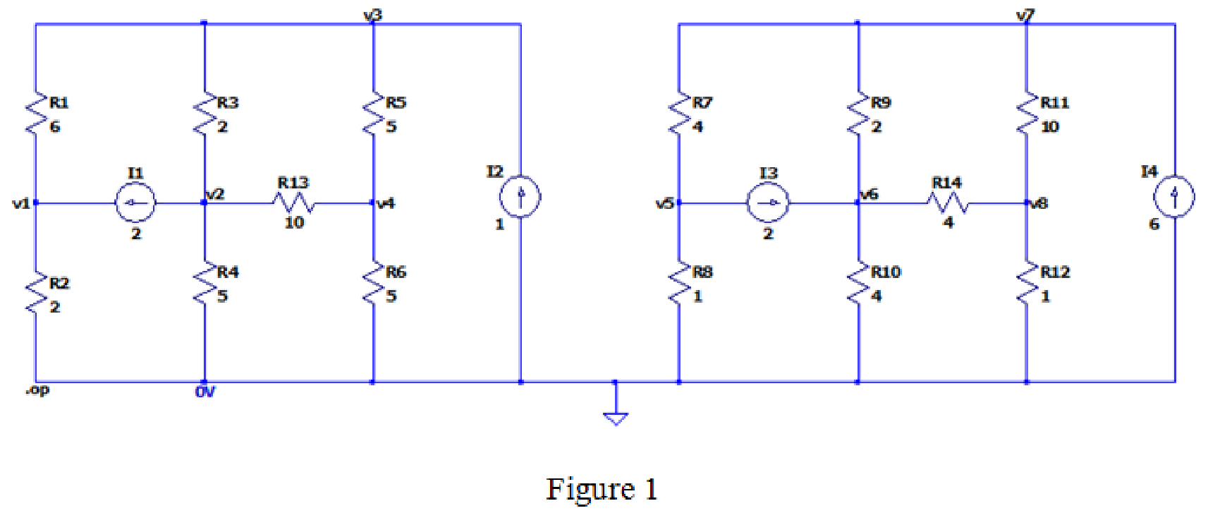
The output after simulating the LTspice circuit is,
--- Operating Point ---
V(v3): 0.310881 voltage
V(v1): 3.07772 voltage
V(v2): -2.34888 voltage
V(v4): -0.345423 voltage
V(v7): 13.0951 voltage
V(v5): 1.01901 voltage
V(v6): 9.21673 voltage
V(v8): 2.67681 voltage
I(I3): 2 device_current
I(I1): 2 device_current
I(I4): 6 device_current
I(I2): 1 device_current
I(R14): -1.63498 device_current
I(R13): 0.200345 device_current
I(R12): 2.67681 device_current
I(R11): 1.04183 device_current
I(R10): 2.30418 device_current
I(R9): 1.93916 device_current
I(R8): 1.01901 device_current
I(R7): 3.01901 device_current
I(R6): -0.0690846 device_current
I(R5): 0.131261 device_current
I(R4): -0.469775 device_current
I(R3): 1.32988 device_current
I(R2): 1.53886 device_current
I(R1): -0.46114 device_current
The both calculated and simulated values are approximately equal.
Conclusion:
Therefore, the solution is verified with the LTspice simulation.
Want to see more full solutions like this?
Chapter 4 Solutions
Loose Leaf for Engineering Circuit Analysis Format: Loose-leaf


- Using the rules for parallel circuits and Ohmslaw, solve for the missing values. ETE1E2E3E4ITl1I2l33.2AI4RT3.582R116R210R3R420PTP1P2P3P4arrow_forwardNeed help with finding paramtersarrow_forward9)The........and the ........are very similar a)engineer's scale rule and architect's scale rule b) engineer's scale rule and the desk ruler c) protractor and adjustable triangle ruler d)architect's scale rule and drafting triangle 10) Graphical abbreviations are used on electrical diagrams to illustrate the wiring between electrical devices and terminals. The electrical devices are either shown in block diagram form or using commonly defined symbols. a) true b) false [ i need both answer]arrow_forward
- Answer all the questions You have 6 PV panels that each have the same I-V curve (ISC = 5.5 A, VOC = 45 V). (a) How many connection configurations that use all 6 panels are possible? Draw each one. (b) Draw the I-V curves for each of the configurations on one graph. You may draw the curves by hand or use a software of your choice. Clearly label each curve. (c) Assume you are to power a 2.5 Ω load with the panels. Knowing that dimmer sunlight reduces the current output of the cells but not the output voltage, what configuration would be best if you were to build it? Explain your answer.arrow_forwardI need a schematic diagram for this figure.arrow_forwardHow to solve this examplearrow_forward
- please hellp me solve this one. i need to paass this exam please provide a complete and detail solution, please. subject is elecetrical circuts 2. just the number 5 answerarrow_forwardThe issue is a power diversion, I need this solution as soon as possible. It is very necessaryarrow_forwardA. Discuss the importance of power electronics interfaces in microgrid installations B. With the aid of diagram describe DC microgrid C. With the aid of diagram describe AC microgridarrow_forward
- Now we will use this knowledge of the code structure to make an LED Blink! Refer to Task 2 (page 7) steps, schematic and code. Use a 470 22 resistor. Keep in mind that the LED's Cathode is connected to the short leg and the flat side. In this circuit the Cathode is connected to the ground. It could also be connected to +5V although this will result in inverted logic. Anode Cathode Anode (long lead) Cathode (short lead.) flat side or spot Figure 1: LED polarity, credit: (https://rctrains.co.uk/LEDs.htm) Calculate the smallest resistor value assuming a Red LED is used with a forward voltage of 1.8V. These are very conservative numbers so verify that the 470 2 resistor is larger than the calculated minimum. use Arduino write codearrow_forwardConsider a PV Module with 24 solar PV cells with the Size of each 15cm x 10cm are connected in series. Choose the correct statement for the above. (Assume necessary data) a. The output voltage is 12 V, the output power is 540W b. The output voltage is 12 V, the output power is 54W c. The output voltage is 12 V, the output power is 5.4W d. The output voltage is 24 V, the output power is 2.25Warrow_forwardI need helpo with this. I need step by step solutions for this and I cant figure it out. Wire to be used in buildings and homes in the United States is standardized according to the AWGsystem (American Wire Gauge). Wires are assigned a gauge number according to their diameter.The scale ranges from gauge 0000 to gauge 36 in 39 steps. The equation for the wire gauge interms of the wire diameter in millimeters is as follows.Answer the following questions with your group.(a) What is the equation for the diameter in millimeters in terms of the wire gauge N?(b) You have two wires, one that has five times the diameter of the other. By how much do thewire gauges differ for the two wires? (Give your answer to the nearest integer.)arrow_forward
 Delmar's Standard Textbook Of ElectricityElectrical EngineeringISBN:9781337900348Author:Stephen L. HermanPublisher:Cengage Learning
 Power System Analysis and Design (MindTap Course ...Electrical EngineeringISBN:9781305632134Author:J. Duncan Glover, Thomas Overbye, Mulukutla S. SarmaPublisher:Cengage Learning