
Loose Leaf for Engineering Circuit Analysis Format: Loose-leaf
9th Edition
ISBN: 9781259989452
Author: Hayt
Publisher: Mcgraw Hill Publishers
expand_more
expand_more
format_list_bulleted
Videos
Textbook Question
Chapter 4.3, Problem 7P
Determine i1 and i2 in the circuit of Fig 4.21.
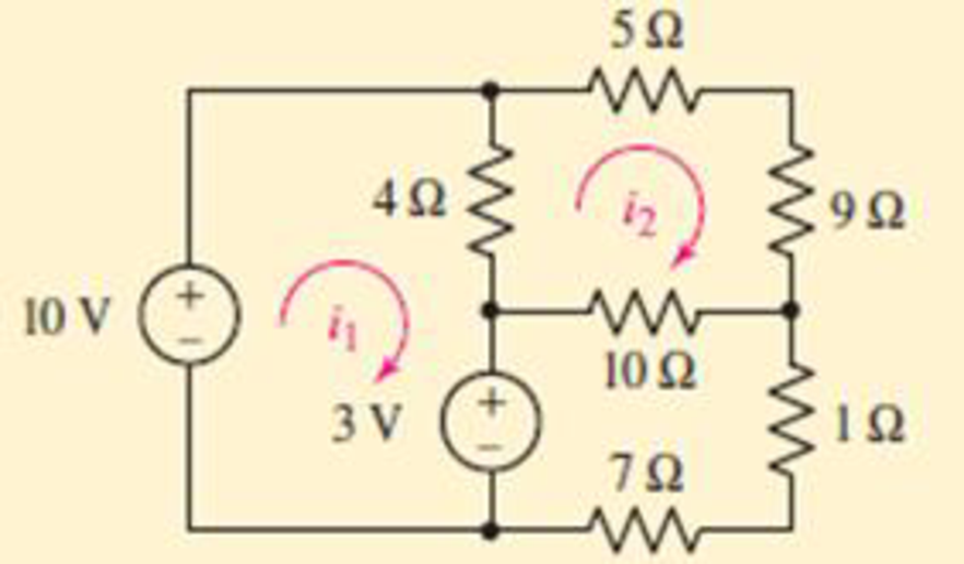
FIGURE 4.21
Expert Solution & Answer
Want to see the full answer?
Check out a sample textbook solution
Students have asked these similar questions
the follow up question wasnt answered properly the question wasnt about the superposition theorm it was about ic1=5<60 /.... and ic2=4+j4 .... can you please explain how you got both formulas in detail? thank you.
Subject:Circuits IShow your solutions help me please so that i can learn too
"NODAL VOLTAGE ANALYSIS"
Please Find the Vo Using NODAL VOLTAGE ANALYSIS thankyou very much!
I've included a cicruit app to check if your answer was correct and close to the value of currents and voltages which is 0.5V thankyou!
I've been testing simple circuits to practice problems using different theorems,I appreciate you very much Thankyou!
Chapter 4 Solutions
Loose Leaf for Engineering Circuit Analysis Format: Loose-leaf
Ch. 4.1 - For the circuit of Fig. 4.3, determine the nodal...Ch. 4.1 - For the circuit of Fig. 4.5, compute the voltage...Ch. 4.1 - For the circuit of Fig. 4.8, determine the nodal...Ch. 4.2 - For the circuit of Fig. 4.11, compute the voltage...Ch. 4.3 - Determine i1 and i2 in the circuit in Fig. 4.19....Ch. 4.3 - Determine i1 and i2 in the circuit of Fig 4.21....Ch. 4.3 - Determine i1 in the circuit of Fig. 4.24 if the...Ch. 4.4 - Determine the current i1 in the circuit of Fig....Ch. 4.4 - Determine v3 in the circuit of Fig. 4.28. FIGURE...Ch. 4 - Solve the following systems of equations: (a) 2v2 ...
Ch. 4 - (a) Solve the following system of equations:...Ch. 4 - (a) Solve the following system of equations:...Ch. 4 - Correct (and verify by running) the following...Ch. 4 - In the circuit of Fig. 4.35, determine the current...Ch. 4 - Calculate the power dissipated in the 1 resistor...Ch. 4 - For the circuit in Fig. 4.37, determine the value...Ch. 4 - With the assistance of nodal analysis, determine...Ch. 4 - Prob. 9ECh. 4 - For the circuit of Fig. 4.40, determine the value...Ch. 4 - Use nodal analysis to find vP in the circuit shown...Ch. 4 - Prob. 12ECh. 4 - Prob. 13ECh. 4 - Determine a numerical value for each nodal voltage...Ch. 4 - Prob. 15ECh. 4 - Using nodal analysis as appropriate, determine the...Ch. 4 - Prob. 17ECh. 4 - Determine the nodal voltages as labeled in Fig....Ch. 4 - Prob. 19ECh. 4 - Prob. 20ECh. 4 - Employing supernode/nodal analysis techniques as...Ch. 4 - Prob. 22ECh. 4 - Prob. 23ECh. 4 - Prob. 24ECh. 4 - Repeat Exercise 23 for the case where the 12 V...Ch. 4 - Prob. 26ECh. 4 - Prob. 27ECh. 4 - Determine the value of k that will result in vx...Ch. 4 - Prob. 29ECh. 4 - Prob. 30ECh. 4 - Prob. 31ECh. 4 - Determine the currents flowing out of the positive...Ch. 4 - Obtain numerical values for the two mesh currents...Ch. 4 - Use mesh analysis as appropriate to determine the...Ch. 4 - Prob. 35ECh. 4 - Prob. 36ECh. 4 - Find the unknown voltage vx in the circuit in Fig....Ch. 4 - Prob. 38ECh. 4 - Prob. 39ECh. 4 - Determine the power dissipated in the 4 resistor...Ch. 4 - (a) Employ mesh analysis to determine the power...Ch. 4 - Define three clockwise mesh currents for the...Ch. 4 - Prob. 43ECh. 4 - Prob. 44ECh. 4 - Prob. 45ECh. 4 - Prob. 46ECh. 4 - Prob. 47ECh. 4 - Prob. 48ECh. 4 - Prob. 49ECh. 4 - Prob. 50ECh. 4 - Prob. 51ECh. 4 - Prob. 52ECh. 4 - For the circuit represented schematically in Fig....Ch. 4 - The circuit of Fig. 4.80 is modified such that the...Ch. 4 - The circuit of Fig. 4.81 contains three sources....Ch. 4 - Solve for the voltage vx as labeled in the circuit...Ch. 4 - Consider the five-source circuit of Fig. 4.83....Ch. 4 - Replace the dependent voltage source in the...Ch. 4 - After studying the circuit of Fig. 4.84, determine...Ch. 4 - Prob. 60ECh. 4 - Employ LTspice (or similar CAD tool) to verify the...Ch. 4 - Employ LTspice (or similar CAD tool) to verify the...Ch. 4 - Employ LTspice (or similar CAD tool) to verify the...Ch. 4 - Verify numerical values for each nodal voltage in...Ch. 4 - Prob. 65ECh. 4 - Prob. 66ECh. 4 - Prob. 67ECh. 4 - Prob. 68ECh. 4 - Prob. 69ECh. 4 - (a) Under what circumstances does the presence of...Ch. 4 - Referring to Fig. 4.88, (a) determine whether...Ch. 4 - Consider the LED circuit containing a red, green,...Ch. 4 - The LED circuit in Fig. 4.89 is used to mix colors...Ch. 4 - A light-sensing circuit is in Fig. 4.90, including...Ch. 4 - Use SPICE to analyze the circuit in Exercise 74 by...
Knowledge Booster


Learn more about
Need a deep-dive on the concept behind this application? Look no further. Learn more about this topic, electrical-engineering and related others by exploring similar questions and additional content below.Similar questions
- Q4: Write mesh equations for the bridge networks shown in figure (4) and (5). 4 k 4 kn 4 k 4 k E 10 V 10V 4 kfl 8 kl 4 kf 8 kn Figure (4) Figure (5)arrow_forwardFigure Q4(a) shows the circuit of a Wheatstone Bridge. Null occurs when R1= 1000 Ω, R2= 700 Ω, R3=500 Ω. Find R4.arrow_forwardLMH_chapter2-part2-homework. X + O File | C:/Users/DELL/Downloads/LMH_chapter2-part2-homework.pdf (D Page view A Read aloud V Draw E Highlight 4 of 15 Erase HW3 4.27 Apply source transformation to find v, in the circuit of Fig. 4.95. 10 Ω 12 2 b 20 Ω a + 50 V 40 Ω 8 A 40 V 11:05 PM O Type here to search A a O 4) E ENG 3/22/2021 近arrow_forward
- 4. Again assume each channel of our power supply can provide 30 V and we want to run a 60 V hair dryer motor. So, we again put the two channels in series for double the voltage. But, if you try this with a non-isolated supply, bad things will happen. Don't do that. The following depicts a circuit where internally the supplies have a common ground (i.e., they are not isolated). Non-Isolated Power Supply Droop2 ww 1mQ Channel2 30V 3.3A max Channel1 30V 3.3A max Droop1 1mQ I I I 1 I Red 1 I 1 Black Red Black JumperCable 26mQ 15A max Motor 1200 Needs -60V (a) Show that the current through the jumper cable will greatly exceed its current rating (which, as shown in the schematic, is 15 A). If this happens for more than a very short time, it will melt. (b) Show that the current through Channell greatly exceeds its maximum current rating. If the short circuit protection circuitry doesnt activate quickly, you will fry your power supply. Hint: You can redraw the circuit in a manner similar to…arrow_forward4.1.Part A: Ohm's law This part aims at checking and proving Ohm's law. Using the fixed 5 V output from the power supply, the 1k, 2k2 and 5k resistors, and considering all the possible unique circuit combinations with these 3 resistors only, conduct the followings: 1. Before the lab session and manually a) design and manually sketch your various circuits using the fixed 5 V power supply (i.e. put the resistors in various parallel or series combinations), b) calculate the current (immediately after the power supply) for all your circuits and find the current and the power dissipated in each of the 3 resistors, c) rank the circuits from maximum to minimum current observed immediately after the power supply, and d) prepare your report and have it with you electronically at the time of your lab session. 2. Before the lab session, and using the LushProjects simulator (see above URL) a) make simulation files and simulate all your circuits, b) check and compare the results with the manual…arrow_forwardQ4 (a) Figure Q4(a) shows a two-port network circuit. (i) (ii) Calculate the admittance parameters of the circuit. Based on the answers in part Q4(a)(i), deduce the equivalent circuit for the circuit in Figure Q4(a). V₁ ö 1092 W 12.5Ω W m 552 W 552 Figure Q4(a) 12 V₂arrow_forward
- a. Using KVL, complete the working equations for the clipping circuits shown in Fig. 4.11 for both positive and negative half-cycles of the input. Simple Parallel Clippers (ldeal Diodles) Biased Parallel Clippers tldeal Diodes) Figure 4.11 Clipping Circuits (Parallel)arrow_forwardD LMH_chapter2-part2-homework. X + O File | C:/Users/DELL/Downloads/LMH_chapter2-part2-homework.pdf D Page view A Read aloud V Draw E Highlight O Erase 3 of 15 HW2 Use superposition to solve for v in the circuit of Fig. 4.87. 2Ω 6 A 4 A 8Ω 4ix 11:00 PM O Type here to search A a O 4) E ENG 3/22/2021arrow_forward"NORTON'S THEOREM" Please Find the Vo Using NORTONS’S THEOREM thankyou very much! I've included a cicruit app to check if your answer was correct and close to the value of currents and voltages which is 0.5V thankyou! I've been testing simple circuits to practice problems using different theorems,I appreciate you very much Thankyou!arrow_forward
- Problem 4.10 Figure 601 $40.0 8011201 1 of 1 Use the node-voltage method to find us in the circuit(Egure 1)if i=57 A and i=14 A Express your answer with the appropriate units. 21 Part B Submit Request Answer μÅ Value 123 Value → Use the node-voltage method to find t in the circut Express your answer with the appropriate units. Units Units ? ?arrow_forwardR4 1kQ R2 2kQ R1 2kQ R6 1kQ V1 12V R5 4kQ R3 4kQ R7 1kQ Show your work, formula and notation: Solve for: RT Notation: RT: IT:arrow_forwardIn each case, multiply out to obtain a sum of products: (Simplify where possible.) (a) (W + X' + Z') (W' + Y') (W' + X + Z') (W + X') (W + Y + Z) (b) (A + B + C + D) (A' + B' + C + D') (A' + C) (A + D) (B + C + D)arrow_forward
arrow_back_ios
SEE MORE QUESTIONS
arrow_forward_ios
Recommended textbooks for you
 Introductory Circuit Analysis (13th Edition)Electrical EngineeringISBN:9780133923605Author:Robert L. BoylestadPublisher:PEARSON
 Delmar's Standard Textbook Of ElectricityElectrical EngineeringISBN:9781337900348Author:Stephen L. HermanPublisher:Cengage Learning
 Programmable Logic ControllersElectrical EngineeringISBN:9780073373843Author:Frank D. PetruzellaPublisher:McGraw-Hill Education
 Fundamentals of Electric CircuitsElectrical EngineeringISBN:9780078028229Author:Charles K Alexander, Matthew SadikuPublisher:McGraw-Hill Education
 Electric Circuits. (11th Edition)Electrical EngineeringISBN:9780134746968Author:James W. Nilsson, Susan RiedelPublisher:PEARSON
 Engineering ElectromagneticsElectrical EngineeringISBN:9780078028151Author:Hayt, William H. (william Hart), Jr, BUCK, John A.Publisher:Mcgraw-hill Education,
Introductory Circuit Analysis (13th Edition)
Electrical Engineering
ISBN:9780133923605
Author:Robert L. Boylestad
Publisher:PEARSON
Delmar's Standard Textbook Of Electricity
Electrical Engineering
ISBN:9781337900348
Author:Stephen L. Herman
Publisher:Cengage Learning
Programmable Logic Controllers
Electrical Engineering
ISBN:9780073373843
Author:Frank D. Petruzella
Publisher:McGraw-Hill Education
Fundamentals of Electric Circuits
Electrical Engineering
ISBN:9780078028229
Author:Charles K Alexander, Matthew Sadiku
Publisher:McGraw-Hill Education
Electric Circuits. (11th Edition)
Electrical Engineering
ISBN:9780134746968
Author:James W. Nilsson, Susan Riedel
Publisher:PEARSON
Engineering Electromagnetics
Electrical Engineering
ISBN:9780078028151
Author:Hayt, William H. (william Hart), Jr, BUCK, John A.
Publisher:Mcgraw-hill Education,
Mesh Current Problems in Circuit Analysis - Electrical Circuits Crash Course - Beginners Electronics; Author: Math and Science;https://www.youtube.com/watch?v=DYg8B-ElK0s;License: Standard Youtube License