
Videos
A light-sensing circuit is in Fig. 4.90, including a resistor that changes value under illumination (photoresistor Rlight) and a variable resistor (potentiometer Rpot). The circuit is in the Wheatstone bridge configuration such that a “balanced” condition results in Vout = 0 for a defined value of incident light and a corresponding value for Rlight. (a) Derive an algebraic expression for Vout in terms of RS, R1, R2, Rlight, and Rpot. (b) Using the numerical values given in the circuit, calculate the value of Rpot required to balance the circuit at 500 lux, where Rlight = 200 Ω. (c) If the resistance of the photoresistor decreases by 2% for a light increase to 600 lux (and assuming the resistance change with light is linear), what will the light level be if you measure Vout = 150 mV?
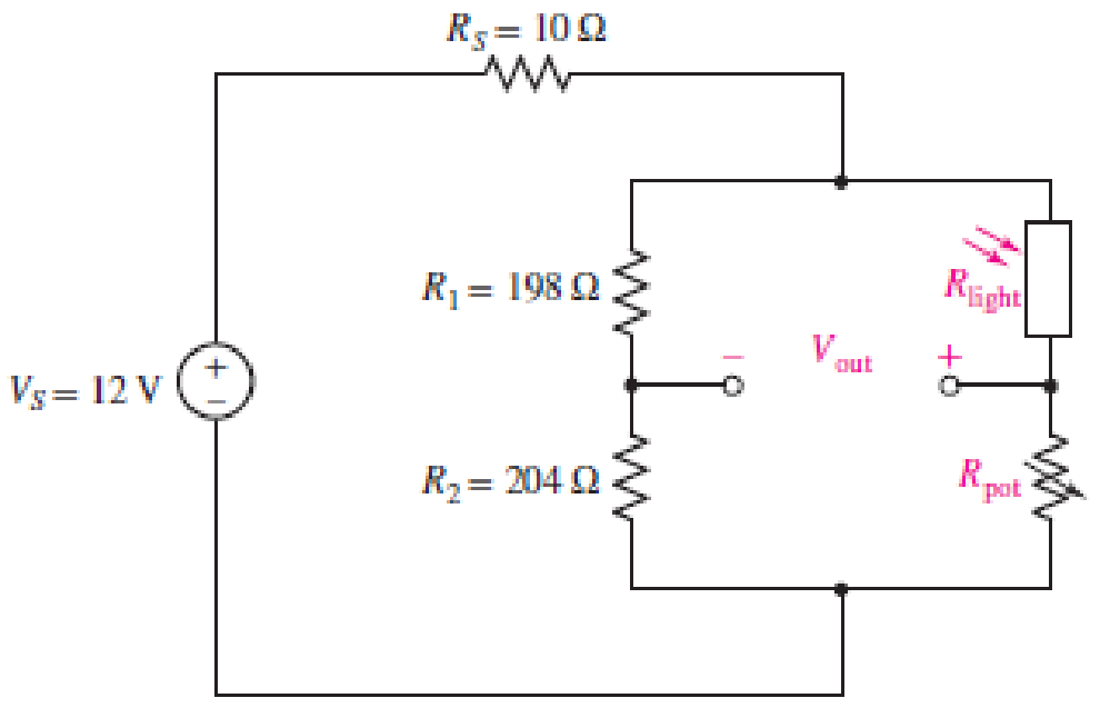
■ FIGURE 4.90
(a)
Write an algebraic expression for the output voltage
Explanation of Solution
Given data:
Refer to Figure 4.90 in the textbook.
Calculation:
The given circuit of Figure 4.90 is redrawn as shown in Figure 1.
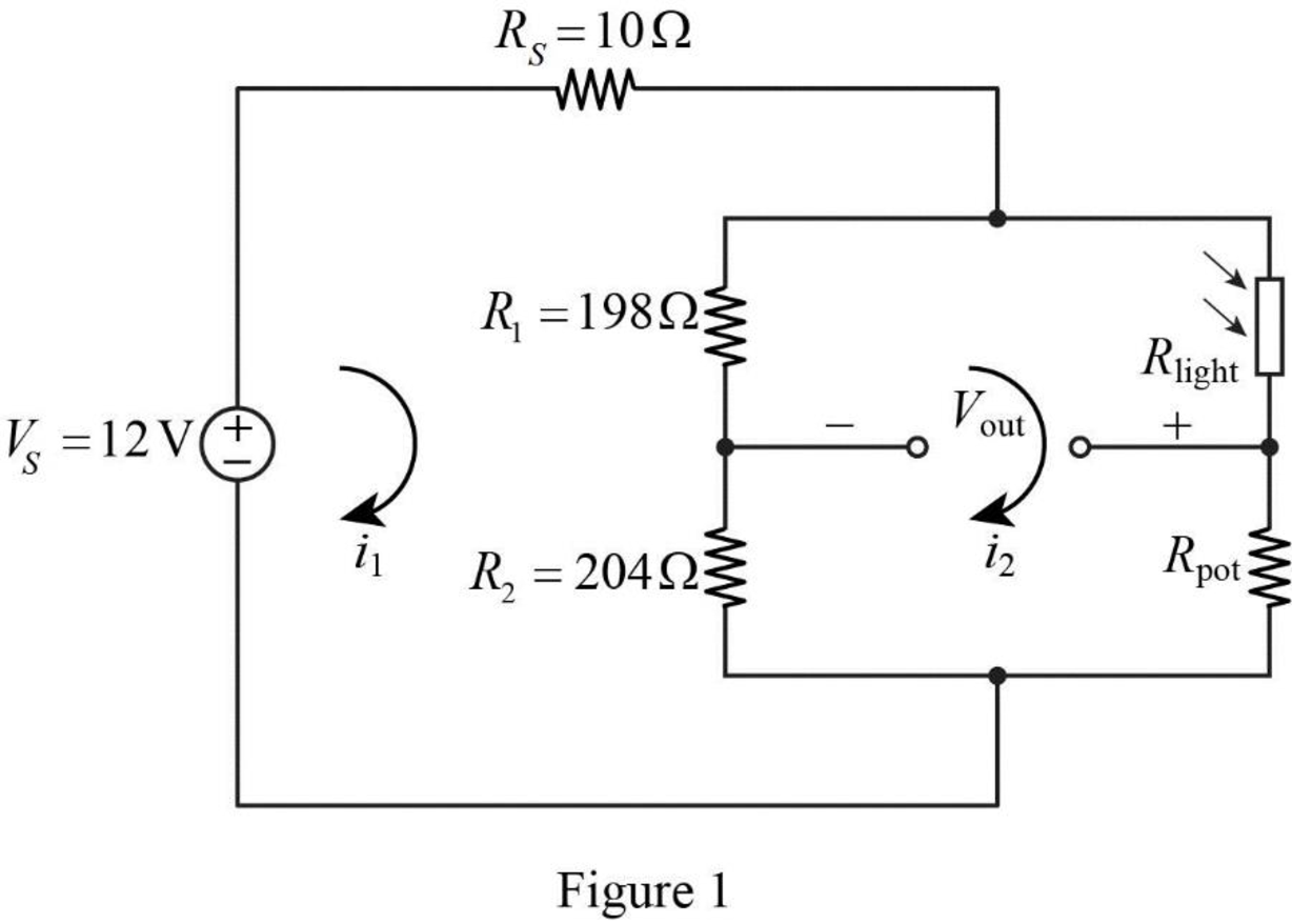
Apply Kirchhoff’s voltage law for the loop current
Apply Kirchhoff’s voltage law for the loop current
Rearrange the equation as follows,
Substitute equation (2) in equation (1).
Rearrange the equation as follows,
Substitute equation (3) in equation (2).
In Figure 1, the output voltage
Substitute equation (3) and (4) in equation (5).
Conclusion:
Thus, the output voltage
(b)
Calculate the value of variable resistor
Answer to Problem 74E
The value of variable resistor
Explanation of Solution
Given data:
Refer to Part (a).
The resistance
For balanced condition,
Calculation:
Refer to Part (a).
Substitute 0 for
Simplify the equation as follows,
Substitute
Conclusion:
Thus, the value of variable resistor
(c)
Find the light level if the resistance of the photoresistor decreases by 2% for a light increase to 600 lux with the measure of output voltage
Answer to Problem 74E
The light level is 760 lux if the resistance of the photoresistor decreases by 2% for a light increase to 600 lux with the measure of output voltage
Explanation of Solution
Given data:
Refer to Part (b).
The variable resistor
The output voltage
Calculation:
When the photoresistor resistance decreases by 2% with a light increase to 600 lux, then
Refer to Part (a), reduce the equation (6) as follows,
Substitute 12 V for
Reduce the equation as follows,
For a linear change, the light level is calculated as follows.
Conclusion:
Thus, the light level is 760 lux if the resistance of the photoresistor decreases by 2% for a light increase to 600 lux with the measure of output voltage
Want to see more full solutions like this?
Chapter 4 Solutions
Loose Leaf for Engineering Circuit Analysis Format: Loose-leaf
Additional Engineering Textbook Solutions
Introductory Circuit Analysis (13th Edition)
Programmable Logic Controllers
ELECTRICITY FOR TRADES (LOOSELEAF)
Basic Engineering Circuit Analysis
Electric Motors and Control Systems
Electric Circuits (10th Edition)


- Quèstion 3 For the following circuit, as we increase the load resistance R, the diode current Ip increases. Ip tVD- Vs 3RL True False Moving to another question will save this response. Ciparrow_forwardThe following symbol denotes a p-n type junction diode, where current favors flowing through one direction than the other (positive current flows from Anode to Cathode side). p-type silicon n-type silicon Anode Cathode Anode Cathode Consider the circuit shown below, where S is the source of alternating positive current, and Load represents any circuit component that does work when voltage is applied. A D4 D, S D2 ILoad В Using the symbols S, A, B, D1, D2, D3, D4 and arrows, write the order the current passes through the components when: a) the current flows from S to A (S→A>..→S) b) the current flows from S to B (S→B→...→S)arrow_forwardLEDs (Light Emitting Diodes) conduct electricity in only one direction. A white LED tends tohave a voltage of 3.5, red 1.8 volts, blue 3.6 volts, and 2.1 volts for a green, orange or yellow LED.(a) You are to design a circuit comprising of 10 RED LEDs that can be powered up by a 12 Vbattery. Choose series/parallel combinations of LEDs and appropriate resistors. Note: You have to draw the complete circuit diagram showing the configuration includingbattery, all LEDs and resistors (with standard values only) and the power rating of eachresistor used. (b) Repeat part (a) if you have only BLUE lights in the circuit.(c) How will your design of part (a) change if you have different color LEDs (3 Red, 5 Blue,One Green and One Orange LED)?(d) Repeat part (c) if you have 230 V AC power instead of 12 V DCarrow_forward
- 3. Based on an old quiz problem related to half-wave rectifièr design. You may need your design if we have cold weather this winter. for charging your 12 VDC car battery. You are to design a battery eharger for safe operation in a damp garage environment to use RI Current Ling Resor R1 TXI Fuse 12 Vot Car Bater Metal Case Design specifications include: (a) Input is a 110rms VAC. (Vp=110x v2) at 60 Hz from a three wire service that meets the National Electrical Code. (b) Output is a nominal 12 volts VDC at the cathode of the diode. (c) Specify a resistor, R, to limit the maximum battery charging current to 10 amperes into the 12 volt car battery assuming the battery is completely dead (0 volts) when you first connect the charger. A not uncommon occurrence over the last two weeks of sub-zero temperatures. (d) There is no ripple voltage design specification. Explain why this is unnecessary in this application. (e) The battery charger case is metal. (f) Assume a diode with VF= 0.7 V (g)…arrow_forwardOAP 61. For the circuit below, write an expression for vo in terms of the input voltages and resistors. Don't make any assumptions about certain resistors being equal. (This actually makes the problem easier.) V3 V2 V1 Rc RB W RA RD WWW + Voarrow_forwardFor circuits (a) and (b) in Figure 4, name the circuit and define the output voltage v_o given that the input v_1 = sinwt and v_2 = 3coswt. Do %3D this by matching the given description to the appropriate roman number. 0,2 MO 500 kn I MI Ị Ch 10 kt (b) (a) Inverting Amplifier 50 simut (15 sin t - cosaut ) 51sinaut 3 sin ut- cos ut 15 sin ut - cos ut Summing Integrator (- cos ut + 15 sin aut)/ Non-inverting Amplifier 14 Summing Differentiator Figure 4. Choose... + Input Figure 4(b) Choose... + Name Figure 4(a) Choose... +arrow_forward
- B=80 Vbe=0,7V a) for Vceq=6V find V1 b) for 3V<Vceq>9V find V1 value rangearrow_forward4. circuitsarrow_forward4.2 For the circuits shown in Fig. P4.2 using ideal diodes, find the values of the voltages and currents indicated. 4. +1 Vo- +2 Vo- D₁ K K D₂ (a) • 2 ΚΩ -5 V -OV +1 Vo +2 Vo K 2 (b) des. +5 V 2 ΚΩ -OVarrow_forward
- (b) The ac voltmeter specification described below is used to measure the voltage across the 50k resistor R3 in the circuit shown in Figure Q4(b). What is the minimum voltage reading that should be observed by AC Voltmeter? The ac voltmeter specification has: • Full-wave rectification • 100µA meter movement 120V range • Limiting error of ± 5% at full scale 10k www R1 V = 120Vrms Figure Q4(b) R₂15k R350karrow_forwardWhat is the function of the circuit? Answer in minimized sum of productsarrow_forwardan | Schoc X O https://ti-submission-google.a x submission-google.app.schoology.com/assignment/student/59013660 M maaoun4@hawkm. Course: Student R.. Current Students.. 6 Home | Schoology M Inbox (2,780) - 20. Q Student Portal D DocHub - Circuits Lab Simulation - 10382745 * ew Insert Format Tools Add-ons Help Last edit was made 10 minutes ago by Zainab Chebib Comic San. A E = = = E E - E - E E 100% - Normal text 12 I 3 I.. 4 10. Keep Te vUTTery vurue Tre sume unu vuru uriTTIer puruneI Cirtur TIEXT TO TIE TrST puruner circuit using 3 light bulbs. 19. Compare the brightness of 2 light bulbs wired in parallel relative to the brightness of 3 light bulbs wired in parallel. Tap circuit element to edit. a. Based on the length of the light rays, when a third light bulb is added in parallel the brightness of each bulb MacBook Pro 吕口 F10 F7 F2 F4 & * %23 3 24 4. 5 6 E Y U D F G H J K Larrow_forward
 Introductory Circuit Analysis (13th Edition)Electrical EngineeringISBN:9780133923605Author:Robert L. BoylestadPublisher:PEARSON
 Delmar's Standard Textbook Of ElectricityElectrical EngineeringISBN:9781337900348Author:Stephen L. HermanPublisher:Cengage Learning
 Programmable Logic ControllersElectrical EngineeringISBN:9780073373843Author:Frank D. PetruzellaPublisher:McGraw-Hill Education
 Fundamentals of Electric CircuitsElectrical EngineeringISBN:9780078028229Author:Charles K Alexander, Matthew SadikuPublisher:McGraw-Hill Education
 Electric Circuits. (11th Edition)Electrical EngineeringISBN:9780134746968Author:James W. Nilsson, Susan RiedelPublisher:PEARSON
 Engineering ElectromagneticsElectrical EngineeringISBN:9780078028151Author:Hayt, William H. (william Hart), Jr, BUCK, John A.Publisher:Mcgraw-hill Education,