
Loose Leaf for Engineering Circuit Analysis Format: Loose-leaf
9th Edition
ISBN: 9781259989452
Author: Hayt
Publisher: Mcgraw Hill Publishers
expand_more
expand_more
format_list_bulleted
Concept explainers
Videos
Textbook Question
Chapter 4, Problem 59E
After studying the circuit of Fig. 4.84, determine the total number of simultaneous equations that must be solved to determine voltages v1 and v3 using (a) nodal analysis; (b) mesh analysis.
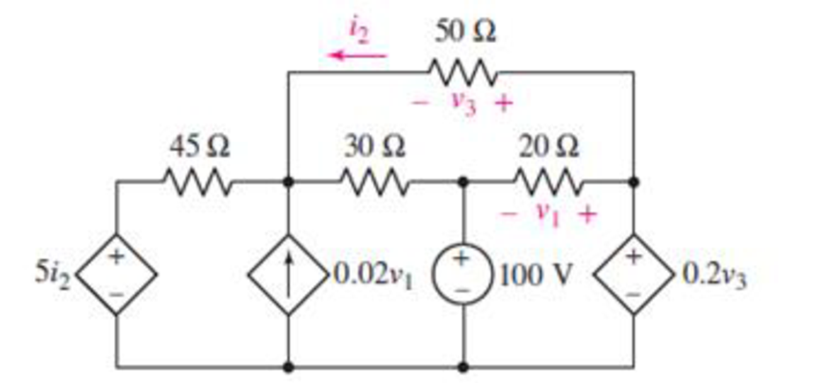
FIGURE 4.84
Expert Solution & Answer
Want to see the full answer?
Check out a sample textbook solution
Students have asked these similar questions
"SUPERPOSITION THEOREM"
Please Find the Vo Using SUPERPOSITION THEOREM thankyou very much!
I've included a cicruit app to check if your answer was correct and close to the value of currents and voltages which is 0.5V thankyou!
I've been testing simple circuits to practice problems using different theorems,I appreciate you very much Thankyou!
Solve step by steo a) and b) please
a) Determine Vs and Rs from a voltage source equivalent to a current source with Is = 500 mA and Rs = 600 Ω
b) Determine Is and Rs of a current source equivalent to a voltage source with Vs = 13V and Rs = 10Ω
Q4: For the circuit shown in figure (3), calculate V and I.
20 V
30
Figure (3)
Chapter 4 Solutions
Loose Leaf for Engineering Circuit Analysis Format: Loose-leaf
Ch. 4.1 - For the circuit of Fig. 4.3, determine the nodal...Ch. 4.1 - For the circuit of Fig. 4.5, compute the voltage...Ch. 4.1 - For the circuit of Fig. 4.8, determine the nodal...Ch. 4.2 - For the circuit of Fig. 4.11, compute the voltage...Ch. 4.3 - Determine i1 and i2 in the circuit in Fig. 4.19....Ch. 4.3 - Determine i1 and i2 in the circuit of Fig 4.21....Ch. 4.3 - Determine i1 in the circuit of Fig. 4.24 if the...Ch. 4.4 - Determine the current i1 in the circuit of Fig....Ch. 4.4 - Determine v3 in the circuit of Fig. 4.28. FIGURE...Ch. 4 - Solve the following systems of equations: (a) 2v2 ...
Ch. 4 - (a) Solve the following system of equations:...Ch. 4 - (a) Solve the following system of equations:...Ch. 4 - Correct (and verify by running) the following...Ch. 4 - In the circuit of Fig. 4.35, determine the current...Ch. 4 - Calculate the power dissipated in the 1 resistor...Ch. 4 - For the circuit in Fig. 4.37, determine the value...Ch. 4 - With the assistance of nodal analysis, determine...Ch. 4 - Prob. 9ECh. 4 - For the circuit of Fig. 4.40, determine the value...Ch. 4 - Use nodal analysis to find vP in the circuit shown...Ch. 4 - Prob. 12ECh. 4 - Prob. 13ECh. 4 - Determine a numerical value for each nodal voltage...Ch. 4 - Prob. 15ECh. 4 - Using nodal analysis as appropriate, determine the...Ch. 4 - Prob. 17ECh. 4 - Determine the nodal voltages as labeled in Fig....Ch. 4 - Prob. 19ECh. 4 - Prob. 20ECh. 4 - Employing supernode/nodal analysis techniques as...Ch. 4 - Prob. 22ECh. 4 - Prob. 23ECh. 4 - Prob. 24ECh. 4 - Repeat Exercise 23 for the case where the 12 V...Ch. 4 - Prob. 26ECh. 4 - Prob. 27ECh. 4 - Determine the value of k that will result in vx...Ch. 4 - Prob. 29ECh. 4 - Prob. 30ECh. 4 - Prob. 31ECh. 4 - Determine the currents flowing out of the positive...Ch. 4 - Obtain numerical values for the two mesh currents...Ch. 4 - Use mesh analysis as appropriate to determine the...Ch. 4 - Prob. 35ECh. 4 - Prob. 36ECh. 4 - Find the unknown voltage vx in the circuit in Fig....Ch. 4 - Prob. 38ECh. 4 - Prob. 39ECh. 4 - Determine the power dissipated in the 4 resistor...Ch. 4 - (a) Employ mesh analysis to determine the power...Ch. 4 - Define three clockwise mesh currents for the...Ch. 4 - Prob. 43ECh. 4 - Prob. 44ECh. 4 - Prob. 45ECh. 4 - Prob. 46ECh. 4 - Prob. 47ECh. 4 - Prob. 48ECh. 4 - Prob. 49ECh. 4 - Prob. 50ECh. 4 - Prob. 51ECh. 4 - Prob. 52ECh. 4 - For the circuit represented schematically in Fig....Ch. 4 - The circuit of Fig. 4.80 is modified such that the...Ch. 4 - The circuit of Fig. 4.81 contains three sources....Ch. 4 - Solve for the voltage vx as labeled in the circuit...Ch. 4 - Consider the five-source circuit of Fig. 4.83....Ch. 4 - Replace the dependent voltage source in the...Ch. 4 - After studying the circuit of Fig. 4.84, determine...Ch. 4 - Prob. 60ECh. 4 - Employ LTspice (or similar CAD tool) to verify the...Ch. 4 - Employ LTspice (or similar CAD tool) to verify the...Ch. 4 - Employ LTspice (or similar CAD tool) to verify the...Ch. 4 - Verify numerical values for each nodal voltage in...Ch. 4 - Prob. 65ECh. 4 - Prob. 66ECh. 4 - Prob. 67ECh. 4 - Prob. 68ECh. 4 - Prob. 69ECh. 4 - (a) Under what circumstances does the presence of...Ch. 4 - Referring to Fig. 4.88, (a) determine whether...Ch. 4 - Consider the LED circuit containing a red, green,...Ch. 4 - The LED circuit in Fig. 4.89 is used to mix colors...Ch. 4 - A light-sensing circuit is in Fig. 4.90, including...Ch. 4 - Use SPICE to analyze the circuit in Exercise 74 by...
Knowledge Booster


Learn more about
Need a deep-dive on the concept behind this application? Look no further. Learn more about this topic, electrical-engineering and related others by exploring similar questions and additional content below.Similar questions
- Q4(a) For the circuit shown in Figure Q4 (a), use superposition theorem to find voltage vo (b) 2A1 15 V 10 Q2 + 892 4 A Figure Q4 (a) 4 A For the circuit shown in Figure Q4 (b), find the Thevenin's equivalent with respect to terminals "a-b". 3Ω 3 Ω www 12 V Figure Q4 (b) 502 ww 69 barrow_forwardQ4. For the below circuit, determine: (a) The Thevenin equivalent circuit as seen from a-b. (b) The value of R and Ps for maximum power transfer to R₁ 40V 402 m 292 m 1210 a b R₁arrow_forwardThe Superposition Principle allows to find specific information in certain branches of an electrical circuit. In the case of the following circuit, by means of this principle, determine what the voltage will be at the resistor R1 terminals answer: VR1 = 508,8 Varrow_forward
- Q4(a) For the circuit shown in Figure Q4 (a), find the Thevenin equivalent with respect to terminals "a-b". 2 A 20 Ω ww 120 V 40 2 12 2 Figure Q4 (a) wwarrow_forwardObtain numerical values for the two mesh currents ij and iz in the circuit shown in Fig. 4.61. 32 5 V iz 12 V 14 2arrow_forwardi, = 12= 76 When v, = 24 V, 24 i, = iz = 76 showing that when the source value is doubled, i, doubles. PRACTICE PROBLEM4.1 VI Va 6Ω 15 and i, = 30 A. %3D For the circuit in Fig. 4.3, find v, when i, Answer: 10 V. 20 V. is 22 42 Figure 4.3 For Practice Prob. 4.1. https://www.facebook.com/Eng.ahmed.shehab3 alanillla aoal https://www.facebook.com/eng.ahmed.sh94/arrow_forward
- Using Thevenin's theorem, find the equivalent circuit to the left Fig. 4.30. Then find Practice: 9.1 the terminals in the circuit in 12 V 2A 40 10 VTh=6 V, RTh = 3 2, i = 1.5 A. Answer: %3D %3Darrow_forward10 mA 1.5 ΚΩ M 1kΩ www 2 ΚΩ 20 mA RL W Q4) For the circuit shown above, find the following: a) The Thevenin equivalent circuit as seen by the load resistance "RL" b) The Norton equivalent circuit as seen by the load resistance "RL" c) The load resistance "R₁" that would absorb maximum power d) The value of the maximum power absorbed by the load found in (c)arrow_forwardshows a circuit containing a dependent voltage source and an independentcurrent source. Explain the steps that need to be taken to obtain the current passingthrough 1kΩ by applying the Mesh Analysis method.arrow_forward
- 4. Again assume each channel of our power supply can provide 30 V and we want to run a 60 V hair dryer motor. So, we again put the two channels in series for double the voltage. But, if you try this with a non-isolated supply, bad things will happen. Don't do that. The following depicts a circuit where internally the supplies have a common ground (i.e., they are not isolated). Non-Isolated Power Supply Droop2 ww 1mQ Channel2 30V 3.3A max Channel1 30V 3.3A max Droop1 1mQ I I I 1 I Red 1 I 1 Black Red Black JumperCable 26mQ 15A max Motor 1200 Needs -60V (a) Show that the current through the jumper cable will greatly exceed its current rating (which, as shown in the schematic, is 15 A). If this happens for more than a very short time, it will melt. (b) Show that the current through Channell greatly exceeds its maximum current rating. If the short circuit protection circuitry doesnt activate quickly, you will fry your power supply. Hint: You can redraw the circuit in a manner similar to…arrow_forwardYou are required to analyze the circuit given below, using Thevenin's theorem. You can use any technique to simplify the circuit if required (without disturbing Vo). Please address the followings: a) Compute open circuit voltage Voc across a-b terminals. b) Compute short circuit current (Iah) by short-circuiting the terminals a-b. c) Compute RTH using the values of Voc and Ish. [1 mark] d) Recompute RTH by inserting 1A-current source across a-b terminals. 0.25 Vo 20 18V 3Ω. Voarrow_forwardSolve the given circuit (calculate all of the voltage and the current variables) using two methods. a) Solve using mesh-current method. b) Solve using node-voltage method. R, i,- 4i, R, R1 = 10 kQ R2 = 20 kQ R3 = 30 kQ R4 = 40 kQ R5 = 50 kQ V6 = 20 V V, = 4 V Is = 1 A V, R, R,arrow_forward
arrow_back_ios
SEE MORE QUESTIONS
arrow_forward_ios
Recommended textbooks for you
 Introductory Circuit Analysis (13th Edition)Electrical EngineeringISBN:9780133923605Author:Robert L. BoylestadPublisher:PEARSON
 Delmar's Standard Textbook Of ElectricityElectrical EngineeringISBN:9781337900348Author:Stephen L. HermanPublisher:Cengage Learning
 Programmable Logic ControllersElectrical EngineeringISBN:9780073373843Author:Frank D. PetruzellaPublisher:McGraw-Hill Education
 Fundamentals of Electric CircuitsElectrical EngineeringISBN:9780078028229Author:Charles K Alexander, Matthew SadikuPublisher:McGraw-Hill Education
 Electric Circuits. (11th Edition)Electrical EngineeringISBN:9780134746968Author:James W. Nilsson, Susan RiedelPublisher:PEARSON
 Engineering ElectromagneticsElectrical EngineeringISBN:9780078028151Author:Hayt, William H. (william Hart), Jr, BUCK, John A.Publisher:Mcgraw-hill Education,
Introductory Circuit Analysis (13th Edition)
Electrical Engineering
ISBN:9780133923605
Author:Robert L. Boylestad
Publisher:PEARSON
Delmar's Standard Textbook Of Electricity
Electrical Engineering
ISBN:9781337900348
Author:Stephen L. Herman
Publisher:Cengage Learning
Programmable Logic Controllers
Electrical Engineering
ISBN:9780073373843
Author:Frank D. Petruzella
Publisher:McGraw-Hill Education
Fundamentals of Electric Circuits
Electrical Engineering
ISBN:9780078028229
Author:Charles K Alexander, Matthew Sadiku
Publisher:McGraw-Hill Education
Electric Circuits. (11th Edition)
Electrical Engineering
ISBN:9780134746968
Author:James W. Nilsson, Susan Riedel
Publisher:PEARSON
Engineering Electromagnetics
Electrical Engineering
ISBN:9780078028151
Author:Hayt, William H. (william Hart), Jr, BUCK, John A.
Publisher:Mcgraw-hill Education,
Nodal Analysis for Circuits Explained; Author: Engineer4Free;https://www.youtube.com/watch?v=f-sbANgw4fo;License: Standard Youtube License