
Concept explainers
Videos
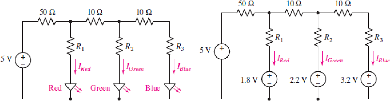
Consider the LED circuit containing a red, green, and blue LED as shown in Fig. 4.89. The LEDs behave much like a voltage source resulting in the circuit in Fig. 4.89, where the light output from each LED will be proportional to the current flowing through the LED. (a) Calculate the current flowing through each LED (IRed, IGreen, and IBlue) if R1 = R2 = R3 = 100 Ω. (b) Determine the resistor values R1, R2, and R3 needed to ensure that the LEDs each have a current of 4 mA flowing through them.
FIGURE 4.89
(a)
Find the current flowing through the each LED in the circuit of Figure 4.89.
Answer to Problem 72E
The current flowing through the each LED in the circuit are
Explanation of Solution
Given data:
Refer to Figure 4.89 in the textbook.
Calculation:
The given circuit is redrawn as shown in Figure 1.
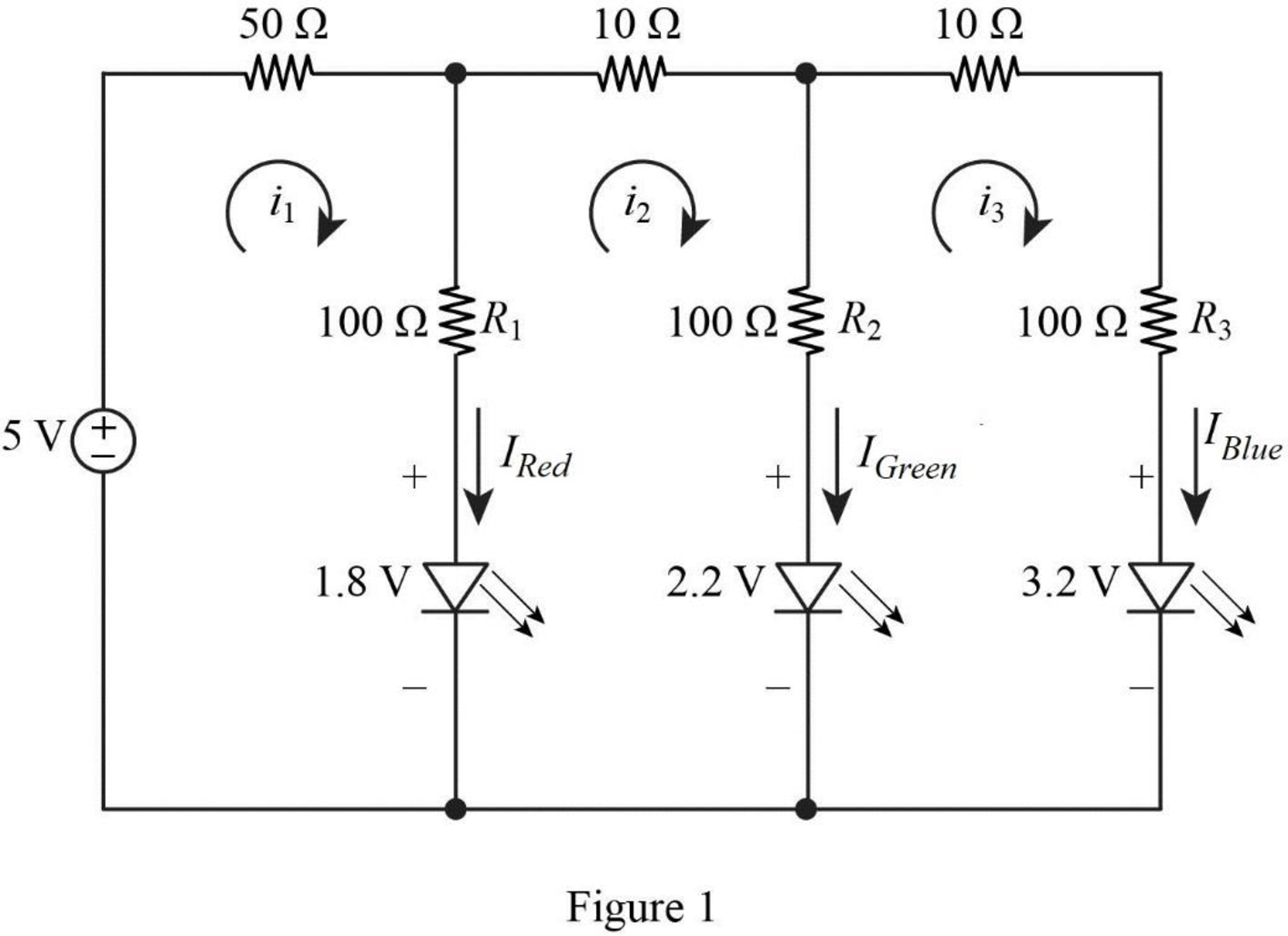
Apply Kirchhoff’s voltage law for loop current
Apply Kirchhoff’s voltage law for loop current
Apply Kirchhoff’s voltage law for loop current
Rearrange the equation (3) as follows,
Substitute equation (4) in equation (1).
Reduce the equation as follows,
Substitute equation (4), (5) in equation (2) to find the current
Reduce the equation as follows,
Substitute
Substitute
In Figure 1, the current
Substitute
In Figure 1, the current
Substitute
In Figure 1, the current
Substitute
Conclusion:
Thus, the current flowing through the each LED in the circuit are
(b)
Find the resistance values of
Answer to Problem 72E
The resistance values of
Explanation of Solution
Given data:
The current,
Calculation:
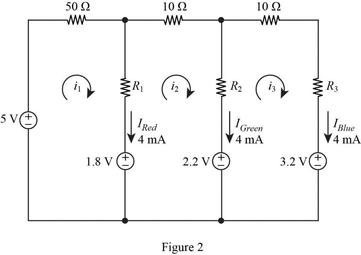
The given circuit is redrawn as shown in Figure 2.
Refer to Part (a),
Substitute
Substitute
Substitute
Apply Kirchhoff’s voltage law for loop current
Substitute
Reduce the equation as follows,
Apply Kirchhoff’s voltage law for loop current
Substitute
Reduce the equation as follows,
Apply Kirchhoff’s voltage law for loop current
Substitute
Reduce the equation as follows,
Conclusion:
Thus, the resistance values of
Want to see more full solutions like this?
Chapter 4 Solutions
Loose Leaf for Engineering Circuit Analysis Format: Loose-leaf
Additional Engineering Textbook Solutions
Programmable Logic Controllers
Electric Circuits (10th Edition)
Electric Circuits. (11th Edition)
Principles and Applications of Electrical Engineering
Basic Engineering Circuit Analysis
Microelectronics: Circuit Analysis and Design


- Q: A wood panel containing 16 solar cells. Calculate the total open circuit voltage and short circuit current coming out of the board and draw the relationship between current and voltages in the following cases a) If you connect each two cells in series and connect the groups in parallel . b) If all four cells are connected in parallel and the groups are linked in succession, noting that each cell has the following characteristics: Vos = 0.75V, Isc = 2 mA %3Darrow_forward4. 5. Three resistors, 110, 53 Q, and R, are connected in series with a 24.0-V battery. The total current flowing through the battery is 0.16 A. (a) Find the value of resistance R. (b) Find the potential difference across each resistor. (c) If the voltage of the battery had been greater than 24.0 V, would your answer to part (a) have been larger or smaller? Explain.arrow_forwardExercise: Sketch the output (Vo) for the circuit of Fig. 4-8 for the input (Vi) shown. Assume ideal diodes. Vi 15 A 0 T/2 -15 t + V₁ Eo 317 R₁ m Fig. (4-8) D₂ E÷WVE₂+10V D₁ R₂ Voarrow_forward
- i need solution very quickly please Can more than one current source be taken as super mesh as in photo? ,if yes i need solution.arrow_forward13. Find the current through each resistor in the circuit of Figure 4.8.11 I need to show all work clearlyarrow_forwardSuppose you measure the terminal voltage of a 2.96-V lithium cell having an internal resistance of 4.10 n by placing a 1.00-kn voltmeter across its terminals. (a) What current flows? (Give your answer to at least four significant figures.) A (b) Find the actual terminal voltage to the nearest 0.001 V. (Give your answer to at least four significant figures.) V (c) To see how close the measured terminal voltage is to the emf, calculate their difference.arrow_forward
- 1. Two identical batteries are available. If the batteries are connected in series and a voltmeter is used to measure its terminal voltage, the voltmeter reads 18 V. If the batteries are connected in series to supply power to load R, R receives 6 A. If the batteries are connected in parallel to supply power to the same load R, R receives 10/3 A Find the Emf (E) and internal resistance (r) of each battery and the value of R.arrow_forwardA Zener diode with a 2.2V Zener voltage is used to build the circuit below. Calculate: (a) The current lz (b) The voltage V₂ (c) The power generated by the 20mA current source 1₂ 20 mA 100 Ω ww 100 Ω + V₂arrow_forwardPlease show the complete solution. Thank you so much Voltage Multipliers (electronics)arrow_forward
- In the following Figure, the current in resistance R, is i,= 14A and the resistances are R, =R, = R; = 20 ohm, R. = 1.6 ohm, R; = 80 ohm, and R, = 4.00 ohm. What is the enmf of applied voltage of the ideal battery? R R4 Rarrow_forwardR = 4.5KN | = 5µA State the ohmmeter scale when the Im current is 0A, ½ FSD, ¼ FSD and FSD V Ry Rm = 5000 Barrow_forwardEach of the six real batteries in the figure has an emf of 19.5 V and a resistance of 4.21 N. (a) What is the current through the (external) resistance R=4.42 N? (b) What is the potential difference across each battery? (c) What is the power of each battery? (d) At what rate does each battery transfer energy to internal thermal energy? R (a) Number Units (b) Number Units (c) Number Units (d) Number Unitsarrow_forward
 Introductory Circuit Analysis (13th Edition)Electrical EngineeringISBN:9780133923605Author:Robert L. BoylestadPublisher:PEARSON
 Delmar's Standard Textbook Of ElectricityElectrical EngineeringISBN:9781337900348Author:Stephen L. HermanPublisher:Cengage Learning
 Programmable Logic ControllersElectrical EngineeringISBN:9780073373843Author:Frank D. PetruzellaPublisher:McGraw-Hill Education
 Fundamentals of Electric CircuitsElectrical EngineeringISBN:9780078028229Author:Charles K Alexander, Matthew SadikuPublisher:McGraw-Hill Education
 Electric Circuits. (11th Edition)Electrical EngineeringISBN:9780134746968Author:James W. Nilsson, Susan RiedelPublisher:PEARSON
 Engineering ElectromagneticsElectrical EngineeringISBN:9780078028151Author:Hayt, William H. (william Hart), Jr, BUCK, John A.Publisher:Mcgraw-hill Education,