
Loose Leaf for Engineering Circuit Analysis Format: Loose-leaf
9th Edition
ISBN: 9781259989452
Author: Hayt
Publisher: Mcgraw Hill Publishers
expand_more
expand_more
format_list_bulleted
Concept explainers
Videos
Textbook Question
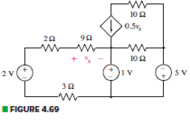
Chapter 4, Problem 42E
Define three clockwise mesh currents for the circuit of Fig. 4.69, and employ mesh analysis to obtain a value for each.
Expert Solution & Answer
Want to see the full answer?
Check out a sample textbook solution
Students have asked these similar questions
Q4/ thyristor connected in a series circuit, the maximum leakage current and recovery charge difference are
5mA and 25µC respectively and all resistors and capacitors are 56K2 and 0.5 µF. If derating factor 32%.
Find the number of thyristor and voltage rating if the voltage rating in particular circuit is 7KV
Given the information appearing in Fig. 4.74, determine:
(a) Ic.
(b) Rc.
(c) Rg-
(d) VCE-
12 V
Ic
RC
RB
O Vc = 6 V
VCE B= 80
IB= 40 µA
4.2 Use Mesh Analysis to find the values of Ix and Vx in the figure.
Chapter 4 Solutions
Loose Leaf for Engineering Circuit Analysis Format: Loose-leaf
Ch. 4.1 - For the circuit of Fig. 4.3, determine the nodal...Ch. 4.1 - For the circuit of Fig. 4.5, compute the voltage...Ch. 4.1 - For the circuit of Fig. 4.8, determine the nodal...Ch. 4.2 - For the circuit of Fig. 4.11, compute the voltage...Ch. 4.3 - Determine i1 and i2 in the circuit in Fig. 4.19....Ch. 4.3 - Determine i1 and i2 in the circuit of Fig 4.21....Ch. 4.3 - Determine i1 in the circuit of Fig. 4.24 if the...Ch. 4.4 - Determine the current i1 in the circuit of Fig....Ch. 4.4 - Determine v3 in the circuit of Fig. 4.28. FIGURE...Ch. 4 - Solve the following systems of equations: (a) 2v2 ...
Ch. 4 - (a) Solve the following system of equations:...Ch. 4 - (a) Solve the following system of equations:...Ch. 4 - Correct (and verify by running) the following...Ch. 4 - In the circuit of Fig. 4.35, determine the current...Ch. 4 - Calculate the power dissipated in the 1 resistor...Ch. 4 - For the circuit in Fig. 4.37, determine the value...Ch. 4 - With the assistance of nodal analysis, determine...Ch. 4 - Prob. 9ECh. 4 - For the circuit of Fig. 4.40, determine the value...Ch. 4 - Use nodal analysis to find vP in the circuit shown...Ch. 4 - Prob. 12ECh. 4 - Prob. 13ECh. 4 - Determine a numerical value for each nodal voltage...Ch. 4 - Prob. 15ECh. 4 - Using nodal analysis as appropriate, determine the...Ch. 4 - Prob. 17ECh. 4 - Determine the nodal voltages as labeled in Fig....Ch. 4 - Prob. 19ECh. 4 - Prob. 20ECh. 4 - Employing supernode/nodal analysis techniques as...Ch. 4 - Prob. 22ECh. 4 - Prob. 23ECh. 4 - Prob. 24ECh. 4 - Repeat Exercise 23 for the case where the 12 V...Ch. 4 - Prob. 26ECh. 4 - Prob. 27ECh. 4 - Determine the value of k that will result in vx...Ch. 4 - Prob. 29ECh. 4 - Prob. 30ECh. 4 - Prob. 31ECh. 4 - Determine the currents flowing out of the positive...Ch. 4 - Obtain numerical values for the two mesh currents...Ch. 4 - Use mesh analysis as appropriate to determine the...Ch. 4 - Prob. 35ECh. 4 - Prob. 36ECh. 4 - Find the unknown voltage vx in the circuit in Fig....Ch. 4 - Prob. 38ECh. 4 - Prob. 39ECh. 4 - Determine the power dissipated in the 4 resistor...Ch. 4 - (a) Employ mesh analysis to determine the power...Ch. 4 - Define three clockwise mesh currents for the...Ch. 4 - Prob. 43ECh. 4 - Prob. 44ECh. 4 - Prob. 45ECh. 4 - Prob. 46ECh. 4 - Prob. 47ECh. 4 - Prob. 48ECh. 4 - Prob. 49ECh. 4 - Prob. 50ECh. 4 - Prob. 51ECh. 4 - Prob. 52ECh. 4 - For the circuit represented schematically in Fig....Ch. 4 - The circuit of Fig. 4.80 is modified such that the...Ch. 4 - The circuit of Fig. 4.81 contains three sources....Ch. 4 - Solve for the voltage vx as labeled in the circuit...Ch. 4 - Consider the five-source circuit of Fig. 4.83....Ch. 4 - Replace the dependent voltage source in the...Ch. 4 - After studying the circuit of Fig. 4.84, determine...Ch. 4 - Prob. 60ECh. 4 - Employ LTspice (or similar CAD tool) to verify the...Ch. 4 - Employ LTspice (or similar CAD tool) to verify the...Ch. 4 - Employ LTspice (or similar CAD tool) to verify the...Ch. 4 - Verify numerical values for each nodal voltage in...Ch. 4 - Prob. 65ECh. 4 - Prob. 66ECh. 4 - Prob. 67ECh. 4 - Prob. 68ECh. 4 - Prob. 69ECh. 4 - (a) Under what circumstances does the presence of...Ch. 4 - Referring to Fig. 4.88, (a) determine whether...Ch. 4 - Consider the LED circuit containing a red, green,...Ch. 4 - The LED circuit in Fig. 4.89 is used to mix colors...Ch. 4 - A light-sensing circuit is in Fig. 4.90, including...Ch. 4 - Use SPICE to analyze the circuit in Exercise 74 by...
Knowledge Booster


Learn more about
Need a deep-dive on the concept behind this application? Look no further. Learn more about this topic, electrical-engineering and related others by exploring similar questions and additional content below.Similar questions
- 4.1.Part A: Ohm's law This part aims at checking and proving Ohm's law. Using the fixed 5 V output from the power supply, the 1k, 2k2 and 5k resistors, and considering all the possible unique circuit combinations with these 3 resistors only, conduct the followings: 1. Before the lab session and manually a) design and manually sketch your various circuits using the fixed 5 V power supply (i.e. put the resistors in various parallel or series combinations), b) calculate the current (immediately after the power supply) for all your circuits and find the current and the power dissipated in each of the 3 resistors, c) rank the circuits from maximum to minimum current observed immediately after the power supply, and d) prepare your report and have it with you electronically at the time of your lab session. 2. Before the lab session, and using the LushProjects simulator (see above URL) a) make simulation files and simulate all your circuits, b) check and compare the results with the manual…arrow_forwardUsing the value of R, calculate the total resistance which is the resistance between terminals X and Y. (LET R= 6.234) (SHOW COMPLETE SOLUTION AND PLS WRITE CLEARLY)arrow_forwardQ4: A: Draw only, a distributer (DC ring distributer) ABCDA is fed from point A with 300 v. The main supplies loads are 175 ampere at point B. 322 ampere at point C and 260 ampere at point D. Then put the value and the direction of the current between each two points, if you know that the current (1) between A and B is 335 Amp.arrow_forward
- Solve step by steo a) and b) please a) Determine Vs and Rs from a voltage source equivalent to a current source with Is = 500 mA and Rs = 600 Ω b) Determine Is and Rs of a current source equivalent to a voltage source with Vs = 13V and Rs = 10Ωarrow_forwardA battery with EMF of 7V and an internal resistance, r=0.08 is connected to a load resistance R=240. Determine its terminal voltage. r www + M Rarrow_forwardSuper-mesh occurs because a source is common to two meshes Select one: O a.dependent O b.voltage O c current O d.independentarrow_forward
- 2) (ch 4 #4 from Nise) Consider a single loop circuit consisting of a 5V de battery, a 1.8 ohm resistor, and a 0.79F capacitor. If the circuit is completed (think closing a switch) at t=0, find the capacitor voltage (in other words, find ve(t) as you did in DS1) in the network as a function of time. (1) Use KVL to find the equation of the circuit in terms of vc. (2) Take the Laplace transform of the equation. (3) Solve this equation for V (s) then take the inverse Laplace transform to get ve (t). Also find the time constant, rise time, and settling time for the capacitor voltage.arrow_forward1. For the fixed-bias configuration of Fig. 4.118, determine: a. IBg' 16 V b. Icg c. VCEg Ico 1.8 k22 510 kQ2 VB IBQ Vc VCEQ B=120 VEarrow_forward(Example 4.8) Determine all node voltages and branch currents assuming = 100. Assume Active +5 V 100 ΚΩ www +10 V 2 ΚΩarrow_forward
- a. Using KVL, complete the working equations for the clipping circuits shown in Fig. 4.11 for both positive and negative half-cycles of the input. Simple Parallel Clippers (ldeal Diodles) Biased Parallel Clippers tldeal Diodes) Figure 4.11 Clipping Circuits (Parallel)arrow_forwardQ4: For the circuit shown in figure (3), calculate V and I. 20 V 30 Figure (3)arrow_forward6:19 Details Network Analysis Ohms Law - Lesson "N1 D e Q E Design Transitions Animations Slide Show Review Home Insert Draw OLayout B A. 4.8 k2 9 kO 20 V 6 kO 12 kº 4 kO 10 k2 a. Calculate the power supplied by the 20 V source. b. Hence or otherwise, determine the energy consumed by the 12 k2 resistor in 2 minu of 86 D Notes go oarrow_forward
arrow_back_ios
SEE MORE QUESTIONS
arrow_forward_ios
Recommended textbooks for you
 Introductory Circuit Analysis (13th Edition)Electrical EngineeringISBN:9780133923605Author:Robert L. BoylestadPublisher:PEARSON
 Delmar's Standard Textbook Of ElectricityElectrical EngineeringISBN:9781337900348Author:Stephen L. HermanPublisher:Cengage Learning
 Programmable Logic ControllersElectrical EngineeringISBN:9780073373843Author:Frank D. PetruzellaPublisher:McGraw-Hill Education
 Fundamentals of Electric CircuitsElectrical EngineeringISBN:9780078028229Author:Charles K Alexander, Matthew SadikuPublisher:McGraw-Hill Education
 Electric Circuits. (11th Edition)Electrical EngineeringISBN:9780134746968Author:James W. Nilsson, Susan RiedelPublisher:PEARSON
 Engineering ElectromagneticsElectrical EngineeringISBN:9780078028151Author:Hayt, William H. (william Hart), Jr, BUCK, John A.Publisher:Mcgraw-hill Education,
Introductory Circuit Analysis (13th Edition)
Electrical Engineering
ISBN:9780133923605
Author:Robert L. Boylestad
Publisher:PEARSON
Delmar's Standard Textbook Of Electricity
Electrical Engineering
ISBN:9781337900348
Author:Stephen L. Herman
Publisher:Cengage Learning
Programmable Logic Controllers
Electrical Engineering
ISBN:9780073373843
Author:Frank D. Petruzella
Publisher:McGraw-Hill Education
Fundamentals of Electric Circuits
Electrical Engineering
ISBN:9780078028229
Author:Charles K Alexander, Matthew Sadiku
Publisher:McGraw-Hill Education
Electric Circuits. (11th Edition)
Electrical Engineering
ISBN:9780134746968
Author:James W. Nilsson, Susan Riedel
Publisher:PEARSON
Engineering Electromagnetics
Electrical Engineering
ISBN:9780078028151
Author:Hayt, William H. (william Hart), Jr, BUCK, John A.
Publisher:Mcgraw-hill Education,
Nodal Analysis for Circuits Explained; Author: Engineer4Free;https://www.youtube.com/watch?v=f-sbANgw4fo;License: Standard Youtube License