
Loose Leaf for Engineering Circuit Analysis Format: Loose-leaf
9th Edition
ISBN: 9781259989452
Author: Hayt
Publisher: Mcgraw Hill Publishers
expand_more
expand_more
format_list_bulleted
Videos
Textbook Question
Chapter 4, Problem 56E
Solve for the voltage vx as labeled in the circuit of Fig. 4.82 using (a) mesh analysis. (b) Repeat using nodal analysis. (c) Which approach was easier, and why?
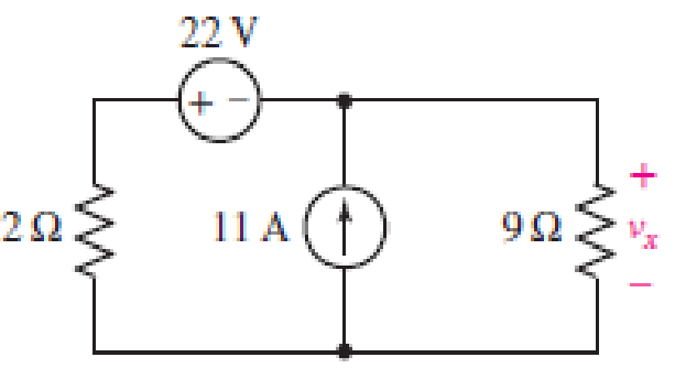
■ FIGURE 4.82
Expert Solution & Answer
Want to see the full answer?
Check out a sample textbook solution
Students have asked these similar questions
Write the system of nodal equations via nodal analysis for this circuit. Make it very detailed explaining the steps and also how nodal analysis should generally be performed in circuits such as this one. And how do we know how many kcl equations we should do ( it's general formula) thank you
"NODAL VOLTAGE ANALYSIS"
Please Find the Vo Using NODAL VOLTAGE ANALYSIS thankyou very much!
I've included a cicruit app to check if your answer was correct and close to the value of currents and voltages which is 0.5V thankyou!
I've been testing simple circuits to practice problems using different theorems,I appreciate you very much Thankyou!
SOLVE THE TOTAL RESISTANCE, RT. (SERIES-PARALLEL)
SOLVE THE TOTAL CURRENT, Ir. (OHM'S LAW)
SHOW THAT VRI + VR4 = 110 V. (VOLTAGE DIVIDER)
SOLVE THE CURRENT IN R4, I. (CURRENT DIVIDER)
V.
I.
II.
III.
IV.
SHOW ALL COMPUTATIONS.
R, = 60 N
%3D
ww
R2 = 40 2 R3 = 20 Q
%3D
ww WW
110 V
I
R,50 ΩΣ
IT
(A)
(ОНМ)
I (in R:)
RT
Vs
VRI
VR4
Vri+VR4
(V)
110
COMPUTED
|MEASURED
% ERROR
110
www
Chapter 4 Solutions
Loose Leaf for Engineering Circuit Analysis Format: Loose-leaf
Ch. 4.1 - For the circuit of Fig. 4.3, determine the nodal...Ch. 4.1 - For the circuit of Fig. 4.5, compute the voltage...Ch. 4.1 - For the circuit of Fig. 4.8, determine the nodal...Ch. 4.2 - For the circuit of Fig. 4.11, compute the voltage...Ch. 4.3 - Determine i1 and i2 in the circuit in Fig. 4.19....Ch. 4.3 - Determine i1 and i2 in the circuit of Fig 4.21....Ch. 4.3 - Determine i1 in the circuit of Fig. 4.24 if the...Ch. 4.4 - Determine the current i1 in the circuit of Fig....Ch. 4.4 - Determine v3 in the circuit of Fig. 4.28. FIGURE...Ch. 4 - Solve the following systems of equations: (a) 2v2 ...
Ch. 4 - (a) Solve the following system of equations:...Ch. 4 - (a) Solve the following system of equations:...Ch. 4 - Correct (and verify by running) the following...Ch. 4 - In the circuit of Fig. 4.35, determine the current...Ch. 4 - Calculate the power dissipated in the 1 resistor...Ch. 4 - For the circuit in Fig. 4.37, determine the value...Ch. 4 - With the assistance of nodal analysis, determine...Ch. 4 - Prob. 9ECh. 4 - For the circuit of Fig. 4.40, determine the value...Ch. 4 - Use nodal analysis to find vP in the circuit shown...Ch. 4 - Prob. 12ECh. 4 - Prob. 13ECh. 4 - Determine a numerical value for each nodal voltage...Ch. 4 - Prob. 15ECh. 4 - Using nodal analysis as appropriate, determine the...Ch. 4 - Prob. 17ECh. 4 - Determine the nodal voltages as labeled in Fig....Ch. 4 - Prob. 19ECh. 4 - Prob. 20ECh. 4 - Employing supernode/nodal analysis techniques as...Ch. 4 - Prob. 22ECh. 4 - Prob. 23ECh. 4 - Prob. 24ECh. 4 - Repeat Exercise 23 for the case where the 12 V...Ch. 4 - Prob. 26ECh. 4 - Prob. 27ECh. 4 - Determine the value of k that will result in vx...Ch. 4 - Prob. 29ECh. 4 - Prob. 30ECh. 4 - Prob. 31ECh. 4 - Determine the currents flowing out of the positive...Ch. 4 - Obtain numerical values for the two mesh currents...Ch. 4 - Use mesh analysis as appropriate to determine the...Ch. 4 - Prob. 35ECh. 4 - Prob. 36ECh. 4 - Find the unknown voltage vx in the circuit in Fig....Ch. 4 - Prob. 38ECh. 4 - Prob. 39ECh. 4 - Determine the power dissipated in the 4 resistor...Ch. 4 - (a) Employ mesh analysis to determine the power...Ch. 4 - Define three clockwise mesh currents for the...Ch. 4 - Prob. 43ECh. 4 - Prob. 44ECh. 4 - Prob. 45ECh. 4 - Prob. 46ECh. 4 - Prob. 47ECh. 4 - Prob. 48ECh. 4 - Prob. 49ECh. 4 - Prob. 50ECh. 4 - Prob. 51ECh. 4 - Prob. 52ECh. 4 - For the circuit represented schematically in Fig....Ch. 4 - The circuit of Fig. 4.80 is modified such that the...Ch. 4 - The circuit of Fig. 4.81 contains three sources....Ch. 4 - Solve for the voltage vx as labeled in the circuit...Ch. 4 - Consider the five-source circuit of Fig. 4.83....Ch. 4 - Replace the dependent voltage source in the...Ch. 4 - After studying the circuit of Fig. 4.84, determine...Ch. 4 - Prob. 60ECh. 4 - Employ LTspice (or similar CAD tool) to verify the...Ch. 4 - Employ LTspice (or similar CAD tool) to verify the...Ch. 4 - Employ LTspice (or similar CAD tool) to verify the...Ch. 4 - Verify numerical values for each nodal voltage in...Ch. 4 - Prob. 65ECh. 4 - Prob. 66ECh. 4 - Prob. 67ECh. 4 - Prob. 68ECh. 4 - Prob. 69ECh. 4 - (a) Under what circumstances does the presence of...Ch. 4 - Referring to Fig. 4.88, (a) determine whether...Ch. 4 - Consider the LED circuit containing a red, green,...Ch. 4 - The LED circuit in Fig. 4.89 is used to mix colors...Ch. 4 - A light-sensing circuit is in Fig. 4.90, including...Ch. 4 - Use SPICE to analyze the circuit in Exercise 74 by...
Additional Engineering Textbook Solutions
Find more solutions based on key concepts
Write the nodal equations for the network of Fig. 8.137 using the general approach. Find the nodal voltages usi...
Introductory Circuit Analysis (13th Edition)
The voltage source of the circuit shown in Fig. P1.29 is given by s(t)=25cos(4104t45)(V). Obtain an expression ...
Fundamentals of Applied Electromagnetics (7th Edition)
When travelers from the USA and Canada visit Europe, they encounter a different power distribution system. Wall...
Electric machinery fundamentals
For the “tank” circuit in Fig. 14.79, find the resonant frequency.
Figure 14.79
For Probs. 14.39, 14.71, and 1...
Fundamentals of Electric Circuits
Assume a telephone signal travels through a cable at two-thirds the speed of light. How long does it take the s...
Electric Circuits (10th Edition)
Explain the main function of each of the following major components of a PLC: a. Processor module (CPU) b. I/O ...
Programmable Logic Controllers
Knowledge Booster


Learn more about
Need a deep-dive on the concept behind this application? Look no further. Learn more about this topic, electrical-engineering and related others by exploring similar questions and additional content below.Similar questions
- Using superposition technique, determine the value of Vx. Refer to figure 4.50I would also appreciate if you'll include another technique (nodal, mesh or source transformation) to compare the answer using superposition.arrow_forwardProblem 4 Consider the circuit in figure 4. a) Isolate RL and draw the Thevenin Equivalent circuit at terminals a-b. b) From part (a), reconnect and determine the value of R, which absorbs the maximum power. c) Find this maximum power if I, is 9A. 4 Vx a Vx+ RL AM-arrow_forwardSolve the given circuit (calculate all of the voltage and the current variables) using + two methods. R, i,- 4i, a) Solve using mesh-current method. b) Solve using node-voltage method. R, R1 = 10 kQ R2 = 20 kQ R3 = 30 k2 || + V7 R, Rs 8, R4 = 40 k2 R5 = 50 kQ V6 = 20 V V7 = 4 V R, %3D Ig = 1 Aarrow_forward
- Q4) By using Nodal analysis, find all voltages and currents. 4 k2 VA 1 k2 4 mA Vc 14 10 V 2 k2 4 k2arrow_forward4. Again assume each channel of our power supply can provide 30 V and we want to run a 60 V hair dryer motor. So, we again put the two channels in series for double the voltage. But, if you try this with a non-isolated supply, bad things will happen. Don't do that. The following depicts a circuit where internally the supplies have a common ground (i.e., they are not isolated). Non-Isolated Power Supply Droop2 ww 1mQ Channel2 30V 3.3A max Channel1 30V 3.3A max Droop1 1mQ I I I 1 I Red 1 I 1 Black Red Black JumperCable 26mQ 15A max Motor 1200 Needs -60V (a) Show that the current through the jumper cable will greatly exceed its current rating (which, as shown in the schematic, is 15 A). If this happens for more than a very short time, it will melt. (b) Show that the current through Channell greatly exceeds its maximum current rating. If the short circuit protection circuitry doesnt activate quickly, you will fry your power supply. Hint: You can redraw the circuit in a manner similar to…arrow_forwardRepeat solving figure 2, using Mesh equation methodarrow_forward
- Using Circuit analysis calculate the following: X, Z, I, V, and V. Calculate Z using the following formula for : z-R +X (Use theoretical values as shown in Figure #1: 25 mH, 1 kn, 5 Vrms @1000HZ). The formulas are shown in Table 1. Include calculations in your lab report. 1.arrow_forwardDetermine the voltage (V1, V2, V3, V4) and current, IY in Figure 4 using Mesh analysis.arrow_forwardWhat is the current read by the ammeter in the circuit below? Let R1 = 1 kiloohm, R2 = 2 kiloohm, R3 = 3 kiloohm, and the emf of the ideal source is 5 volts. Input R1, R2, and R3 for resistors R1, R2, and R3 respectively. Input E for the emf E. Use context clues to figure out if you need to input a numerical value, variable, word, etc. All numerical answers should be in three significant figures. R1 R2 R3 (A First we calculate the current across each resistor. From Ohm's law, we arrive at a general formula for current: |= Plugging in values, the current across the resistor R1 is equal to: (Please note that the current is in milliamperes)arrow_forward
- A 4.0- resistor is connected with a 12-2 resistor and both of these are connected across an ideal dc power supply with voltage V as shown in the figure. If the total current in this circuit is /= 0.8 A, what is the current through the 4.0-2 resistor? Write your answer with 1 place behind the decimal and be sure to include unit. Answer: 4.0 Ω www www 12 Ωarrow_forwardProblem #7) Given the following circuit having the component values: Is = 400 mA, R₁ = 10 Q2, R₂ = 15 92, Determine the current (1₂) in resistor R₂ as shown in the figure using the current divider method. Vs Is R1 12 R2 I₂ = (mA)arrow_forward1. Construct the circuit as shown in Figure 1. Set VS1 and VS2 to 5 V. Measure each of node voltages and record that results in Table below.R1= 1kR2= 3.3k R3= 2.2kR4= 4.7kR5= 1.2k Table 4.2: Nodal Voltage Values Parameter (Volts) THEORITICAL V1 V2 V3 V4 Please draw the current flow in arrow in the circuit. Tqarrow_forward
arrow_back_ios
SEE MORE QUESTIONS
arrow_forward_ios
Recommended textbooks for you
 Introductory Circuit Analysis (13th Edition)Electrical EngineeringISBN:9780133923605Author:Robert L. BoylestadPublisher:PEARSON
 Delmar's Standard Textbook Of ElectricityElectrical EngineeringISBN:9781337900348Author:Stephen L. HermanPublisher:Cengage Learning
 Programmable Logic ControllersElectrical EngineeringISBN:9780073373843Author:Frank D. PetruzellaPublisher:McGraw-Hill Education
 Fundamentals of Electric CircuitsElectrical EngineeringISBN:9780078028229Author:Charles K Alexander, Matthew SadikuPublisher:McGraw-Hill Education
 Electric Circuits. (11th Edition)Electrical EngineeringISBN:9780134746968Author:James W. Nilsson, Susan RiedelPublisher:PEARSON
 Engineering ElectromagneticsElectrical EngineeringISBN:9780078028151Author:Hayt, William H. (william Hart), Jr, BUCK, John A.Publisher:Mcgraw-hill Education,
Introductory Circuit Analysis (13th Edition)
Electrical Engineering
ISBN:9780133923605
Author:Robert L. Boylestad
Publisher:PEARSON
Delmar's Standard Textbook Of Electricity
Electrical Engineering
ISBN:9781337900348
Author:Stephen L. Herman
Publisher:Cengage Learning
Programmable Logic Controllers
Electrical Engineering
ISBN:9780073373843
Author:Frank D. Petruzella
Publisher:McGraw-Hill Education
Fundamentals of Electric Circuits
Electrical Engineering
ISBN:9780078028229
Author:Charles K Alexander, Matthew Sadiku
Publisher:McGraw-Hill Education
Electric Circuits. (11th Edition)
Electrical Engineering
ISBN:9780134746968
Author:James W. Nilsson, Susan Riedel
Publisher:PEARSON
Engineering Electromagnetics
Electrical Engineering
ISBN:9780078028151
Author:Hayt, William H. (william Hart), Jr, BUCK, John A.
Publisher:Mcgraw-hill Education,
[1.2] 8086 Microprocessor Architecture; Author: ThinkX Academy;https://www.youtube.com/watch?v=XX9rDGTBGgQ;License: Standard Youtube License