
Loose Leaf for Engineering Circuit Analysis Format: Loose-leaf
9th Edition
ISBN: 9781259989452
Author: Hayt
Publisher: Mcgraw Hill Publishers
expand_more
expand_more
format_list_bulleted
Concept explainers
Videos
Textbook Question
Chapter 4.1, Problem 3P
For the circuit of Fig. 4.8, determine the nodal voltage v1 if A is (a) 2i1; (b) 2v1.
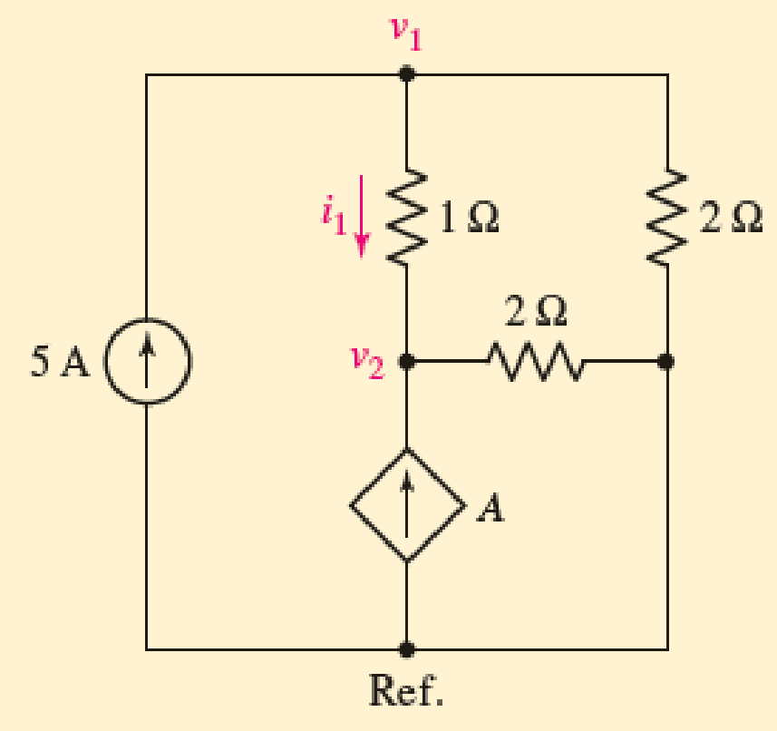
FIGURE 4.8
Expert Solution & Answer
Want to see the full answer?
Check out a sample textbook solution
Students have asked these similar questions
(a)
Simplify the circuit shown in Figure Q4 (a) into single voltage source by
applying source transformation and determine the current, io.
3 A
6 A
20 V
Figure Q4 (a)
Q4/ A)
For the circuit shown below, calculate the current i, the conductance G, and the power P.
30 V (+
5 k2
a. Using KVL, complete the working equations for the clipping circuits shown in Fig. 4.11 for both positive and
negative half-cycles of the input.
Simple Parallel Clippers (ldeal Diodles)
Biased Parallel Clippers tldeal Diodes)
Figure 4.11 Clipping Circuits (Parallel)
Chapter 4 Solutions
Loose Leaf for Engineering Circuit Analysis Format: Loose-leaf
Ch. 4.1 - For the circuit of Fig. 4.3, determine the nodal...Ch. 4.1 - For the circuit of Fig. 4.5, compute the voltage...Ch. 4.1 - For the circuit of Fig. 4.8, determine the nodal...Ch. 4.2 - For the circuit of Fig. 4.11, compute the voltage...Ch. 4.3 - Determine i1 and i2 in the circuit in Fig. 4.19....Ch. 4.3 - Determine i1 and i2 in the circuit of Fig 4.21....Ch. 4.3 - Determine i1 in the circuit of Fig. 4.24 if the...Ch. 4.4 - Determine the current i1 in the circuit of Fig....Ch. 4.4 - Determine v3 in the circuit of Fig. 4.28. FIGURE...Ch. 4 - Solve the following systems of equations: (a) 2v2 ...
Ch. 4 - (a) Solve the following system of equations:...Ch. 4 - (a) Solve the following system of equations:...Ch. 4 - Correct (and verify by running) the following...Ch. 4 - In the circuit of Fig. 4.35, determine the current...Ch. 4 - Calculate the power dissipated in the 1 resistor...Ch. 4 - For the circuit in Fig. 4.37, determine the value...Ch. 4 - With the assistance of nodal analysis, determine...Ch. 4 - Prob. 9ECh. 4 - For the circuit of Fig. 4.40, determine the value...Ch. 4 - Use nodal analysis to find vP in the circuit shown...Ch. 4 - Prob. 12ECh. 4 - Prob. 13ECh. 4 - Determine a numerical value for each nodal voltage...Ch. 4 - Prob. 15ECh. 4 - Using nodal analysis as appropriate, determine the...Ch. 4 - Prob. 17ECh. 4 - Determine the nodal voltages as labeled in Fig....Ch. 4 - Prob. 19ECh. 4 - Prob. 20ECh. 4 - Employing supernode/nodal analysis techniques as...Ch. 4 - Prob. 22ECh. 4 - Prob. 23ECh. 4 - Prob. 24ECh. 4 - Repeat Exercise 23 for the case where the 12 V...Ch. 4 - Prob. 26ECh. 4 - Prob. 27ECh. 4 - Determine the value of k that will result in vx...Ch. 4 - Prob. 29ECh. 4 - Prob. 30ECh. 4 - Prob. 31ECh. 4 - Determine the currents flowing out of the positive...Ch. 4 - Obtain numerical values for the two mesh currents...Ch. 4 - Use mesh analysis as appropriate to determine the...Ch. 4 - Prob. 35ECh. 4 - Prob. 36ECh. 4 - Find the unknown voltage vx in the circuit in Fig....Ch. 4 - Prob. 38ECh. 4 - Prob. 39ECh. 4 - Determine the power dissipated in the 4 resistor...Ch. 4 - (a) Employ mesh analysis to determine the power...Ch. 4 - Define three clockwise mesh currents for the...Ch. 4 - Prob. 43ECh. 4 - Prob. 44ECh. 4 - Prob. 45ECh. 4 - Prob. 46ECh. 4 - Prob. 47ECh. 4 - Prob. 48ECh. 4 - Prob. 49ECh. 4 - Prob. 50ECh. 4 - Prob. 51ECh. 4 - Prob. 52ECh. 4 - For the circuit represented schematically in Fig....Ch. 4 - The circuit of Fig. 4.80 is modified such that the...Ch. 4 - The circuit of Fig. 4.81 contains three sources....Ch. 4 - Solve for the voltage vx as labeled in the circuit...Ch. 4 - Consider the five-source circuit of Fig. 4.83....Ch. 4 - Replace the dependent voltage source in the...Ch. 4 - After studying the circuit of Fig. 4.84, determine...Ch. 4 - Prob. 60ECh. 4 - Employ LTspice (or similar CAD tool) to verify the...Ch. 4 - Employ LTspice (or similar CAD tool) to verify the...Ch. 4 - Employ LTspice (or similar CAD tool) to verify the...Ch. 4 - Verify numerical values for each nodal voltage in...Ch. 4 - Prob. 65ECh. 4 - Prob. 66ECh. 4 - Prob. 67ECh. 4 - Prob. 68ECh. 4 - Prob. 69ECh. 4 - (a) Under what circumstances does the presence of...Ch. 4 - Referring to Fig. 4.88, (a) determine whether...Ch. 4 - Consider the LED circuit containing a red, green,...Ch. 4 - The LED circuit in Fig. 4.89 is used to mix colors...Ch. 4 - A light-sensing circuit is in Fig. 4.90, including...Ch. 4 - Use SPICE to analyze the circuit in Exercise 74 by...
Knowledge Booster


Learn more about
Need a deep-dive on the concept behind this application? Look no further. Learn more about this topic, electrical-engineering and related others by exploring similar questions and additional content below.Similar questions
- Consider the circuit in Figure 4. a) Find the Thevenin equivalent of the network connected to the capacitor C1. b) Find the mathematical equations for the transient behavior of voltage ve(t) and the current ic(t) following the closing of the switch. c) Determine the value of voltage ve at t=100 ms. TCLOSE = 0 R1 1. 21 5k 30 V VI 3k R2 2k R3 C1 33UF R4 1k 0.arrow_forwardDesign a DC voltage source to maintain fixed, stable 15 V, 13.6 V and 12.2 V DC voltages to different loads. In order to realize this request, a transformer having a primer voltage 220 V AC and a seconder voltage 27 V AC (220/27 V AC transformer), some silicon diodes, zener diode and some resistors of 1.5 k2 can be considered in design. a) Draw the network b) Explain the tasks of each component and overall operation in your design. c) Calculate load current and power dissipation for zener diodearrow_forwardThe following symbol denotes a p-n type junction diode, where current favors flowing through one direction than the other (positive current flows from Anode to Cathode side). p-type silicon n-type silicon Anode Cathode Anode Cathode Consider the circuit shown below, where S is the source of alternating positive current, and Load represents any circuit component that does work when voltage is applied. A D4 D, S D2 ILoad В Using the symbols S, A, B, D1, D2, D3, D4 and arrows, write the order the current passes through the components when: a) the current flows from S to A (S→A>..→S) b) the current flows from S to B (S→B→...→S)arrow_forward
- Considering the circuit in the following figure, if V1 varies between -20 V and 0 V and Vb=5V, then the current through V1 is (assume ideal diodes): * D1 D2 4 ko 2 kO V1 Vo Vb -8 V O a. ((V1 +5)/4) mA for V1 2 -5 V and Zero for V1 s -5 V O b. ((V1 -5)) mA for V1 s - 5 V and Zero for V1 2 -5 V Oc. ((V1 +5)/4) mA for V1 s - 5 V and Zero for V1 2 - 5 V O d. ((V1 +5)/4) mA for V1 s 5 V and Zero for V1 2 5 Varrow_forward4.1.Part A: Ohm's law This part aims at checking and proving Ohm's law. Using the fixed 5 V output from the power supply, the 1k, 2k2 and 5k resistors, and considering all the possible unique circuit combinations with these 3 resistors only, conduct the followings: 1. Before the lab session and manually a) design and manually sketch your various circuits using the fixed 5 V power supply (i.e. put the resistors in various parallel or series combinations), b) calculate the current (immediately after the power supply) for all your circuits and find the current and the power dissipated in each of the 3 resistors, c) rank the circuits from maximum to minimum current observed immediately after the power supply, and d) prepare your report and have it with you electronically at the time of your lab session. 2. Before the lab session, and using the LushProjects simulator (see above URL) a) make simulation files and simulate all your circuits, b) check and compare the results with the manual…arrow_forwardA 9-Vdc battery is used in series with a 1-kQ, 100-µA to create a single range ohmmeter. Find the following: a. The series resistance b. The ohmmeter reading at half scalearrow_forward
- QUESTION 2 Find Rth with respect to the terminals a,b for the circuit in Ohms. Figure P4.64 10 Ω 60 V www 40 Ω 8 Ω www a barrow_forward4.3 For the circuits shown in Fig. P4.3 using ideal diodes, find the values of the labeled voltages and currents 20- D₁ ☆ K (d) www|11 1 ΚΩ 01/0 C D₂ K KH D₁ ww|11 -0% 1 ΚΩ D₁ 20-4 ▷ K- D₂ e www/11 1 ΚΩ -0%arrow_forwardLED flashlights use "white" LEDs which have a diode voltage drop of 4.0V. A LED flashlight has the circuit illustrated and will run off several AAA batteries that have a 1.5 VDC rating. a. What is the minimum number of AAA cells needed to turn on the flashlight. b. Would you arrange the batteries in parallel or in series? Vdd R + LED V fritzingarrow_forward
- A PMMC instrument gives 27 mA at full scale reading when a potential difference across its terminals is 44mV. Show that how it can be used (a) as an ammeter for the current measurement in the range of 0-3 A (b) as a 0 - 580V range voltmeter for the voltage measurement. (c) find the multiplying factor of shunt and (d) voltage amplification Rsh shunt resistance R1 series resistance multiplying factor for current voltage amplificationarrow_forward4.47.3 In the circuit shown in the image below, if R1 = 38 Q, R2 = 37 Q, and 1 A, determine the Norton current IN (in A) for its Norton equivalent circuit observed = 1.9 between terminals a and b. R2 R1 +. 20lv Please pay attention: the numbers may change since they are randomized. Your answer should keep 1 place after the decimal point. Your Answer: Answerarrow_forwardA 1) Consider the circuit at right, consisting of two LEDS (one red, one green), which you can model as “practical diodes" with VD= 2.0V (LEDS typically have larger VD's than ordinary Si or Ge diodes). R red green B a) If terminals A and B were connected to a DC source with voltage Vo, what would happen? (Consider applying in both polarities, i.e. +Vo and –Vo, and when VoVD...) b) If the terminals A and B were connected to an AC source with peak voltage VO, what would happen? (Consider both very low frequency: f<~1 Hz – and high-frequency cases.) c) If R = 1 k2, and both diodes have a maximum continuous power dissipation of 0.1 W and a peak inverse voltage VPIV = 20V, what is the maximum DC voltage VDCmax which can be safely applied between A and B?arrow_forward
arrow_back_ios
SEE MORE QUESTIONS
arrow_forward_ios
Recommended textbooks for you
 Introductory Circuit Analysis (13th Edition)Electrical EngineeringISBN:9780133923605Author:Robert L. BoylestadPublisher:PEARSON
 Delmar's Standard Textbook Of ElectricityElectrical EngineeringISBN:9781337900348Author:Stephen L. HermanPublisher:Cengage Learning
 Programmable Logic ControllersElectrical EngineeringISBN:9780073373843Author:Frank D. PetruzellaPublisher:McGraw-Hill Education
 Fundamentals of Electric CircuitsElectrical EngineeringISBN:9780078028229Author:Charles K Alexander, Matthew SadikuPublisher:McGraw-Hill Education
 Electric Circuits. (11th Edition)Electrical EngineeringISBN:9780134746968Author:James W. Nilsson, Susan RiedelPublisher:PEARSON
 Engineering ElectromagneticsElectrical EngineeringISBN:9780078028151Author:Hayt, William H. (william Hart), Jr, BUCK, John A.Publisher:Mcgraw-hill Education,
Introductory Circuit Analysis (13th Edition)
Electrical Engineering
ISBN:9780133923605
Author:Robert L. Boylestad
Publisher:PEARSON
Delmar's Standard Textbook Of Electricity
Electrical Engineering
ISBN:9781337900348
Author:Stephen L. Herman
Publisher:Cengage Learning
Programmable Logic Controllers
Electrical Engineering
ISBN:9780073373843
Author:Frank D. Petruzella
Publisher:McGraw-Hill Education
Fundamentals of Electric Circuits
Electrical Engineering
ISBN:9780078028229
Author:Charles K Alexander, Matthew Sadiku
Publisher:McGraw-Hill Education
Electric Circuits. (11th Edition)
Electrical Engineering
ISBN:9780134746968
Author:James W. Nilsson, Susan Riedel
Publisher:PEARSON
Engineering Electromagnetics
Electrical Engineering
ISBN:9780078028151
Author:Hayt, William H. (william Hart), Jr, BUCK, John A.
Publisher:Mcgraw-hill Education,
Nodal Analysis for Circuits Explained; Author: Engineer4Free;https://www.youtube.com/watch?v=f-sbANgw4fo;License: Standard Youtube License