
Loose Leaf for Engineering Circuit Analysis Format: Loose-leaf
9th Edition
ISBN: 9781259989452
Author: Hayt
Publisher: Mcgraw Hill Publishers
expand_more
expand_more
format_list_bulleted
Concept explainers
Videos
Textbook Question
Chapter 4, Problem 55E
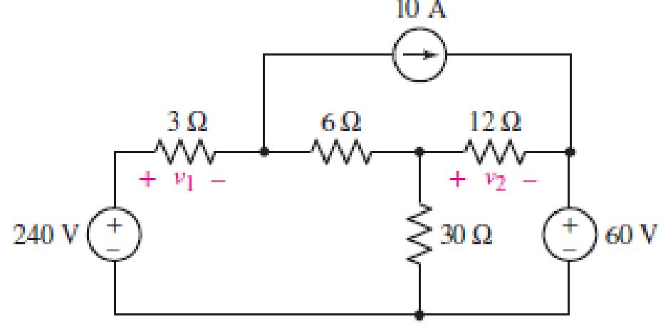
The circuit of Fig. 4.81 contains three sources. (a) As it is now drawn, would nodal or mesh analysis result in fewer equations to determine the voltages v1 and v2? Explain. (b) If the voltage source were replaced with current sources, and the current source replaced with a voltage source, would your answer to part (a) change? Explain.
Expert Solution & Answer
Want to see the full answer?
Check out a sample textbook solution
Students have asked these similar questions
Q4) By using Nodal analysis, find all voltages and currents.
4 k2
VA
1 k2
4 mA
Vc
14
10 V
2 k2
4 k2
Required information
The figure shows a simplified circuit diagram for an automobile. The equivalent resistor R represents the total electrical
load due to spark plugs, lights, radio, fans, starter, rear window defroster, and the like in parallel.
Alternator Battery
14.0 V
R₁
12.0 V
R₂
R
where R₁ = 94.0 m2 and R₂ = 41.0 m2.
What is the terminal voltage of the battery?
Superposition Method. (a) Find the current going down through the 3 ohm resistor. (b) What are the current contributions by the 20-Volt Source, 2-A Source and 16-V Source?-write legibly-show a complete and neat solution
Chapter 4 Solutions
Loose Leaf for Engineering Circuit Analysis Format: Loose-leaf
Ch. 4.1 - For the circuit of Fig. 4.3, determine the nodal...Ch. 4.1 - For the circuit of Fig. 4.5, compute the voltage...Ch. 4.1 - For the circuit of Fig. 4.8, determine the nodal...Ch. 4.2 - For the circuit of Fig. 4.11, compute the voltage...Ch. 4.3 - Determine i1 and i2 in the circuit in Fig. 4.19....Ch. 4.3 - Determine i1 and i2 in the circuit of Fig 4.21....Ch. 4.3 - Determine i1 in the circuit of Fig. 4.24 if the...Ch. 4.4 - Determine the current i1 in the circuit of Fig....Ch. 4.4 - Determine v3 in the circuit of Fig. 4.28. FIGURE...Ch. 4 - Solve the following systems of equations: (a) 2v2 ...
Ch. 4 - (a) Solve the following system of equations:...Ch. 4 - (a) Solve the following system of equations:...Ch. 4 - Correct (and verify by running) the following...Ch. 4 - In the circuit of Fig. 4.35, determine the current...Ch. 4 - Calculate the power dissipated in the 1 resistor...Ch. 4 - For the circuit in Fig. 4.37, determine the value...Ch. 4 - With the assistance of nodal analysis, determine...Ch. 4 - Prob. 9ECh. 4 - For the circuit of Fig. 4.40, determine the value...Ch. 4 - Use nodal analysis to find vP in the circuit shown...Ch. 4 - Prob. 12ECh. 4 - Prob. 13ECh. 4 - Determine a numerical value for each nodal voltage...Ch. 4 - Prob. 15ECh. 4 - Using nodal analysis as appropriate, determine the...Ch. 4 - Prob. 17ECh. 4 - Determine the nodal voltages as labeled in Fig....Ch. 4 - Prob. 19ECh. 4 - Prob. 20ECh. 4 - Employing supernode/nodal analysis techniques as...Ch. 4 - Prob. 22ECh. 4 - Prob. 23ECh. 4 - Prob. 24ECh. 4 - Repeat Exercise 23 for the case where the 12 V...Ch. 4 - Prob. 26ECh. 4 - Prob. 27ECh. 4 - Determine the value of k that will result in vx...Ch. 4 - Prob. 29ECh. 4 - Prob. 30ECh. 4 - Prob. 31ECh. 4 - Determine the currents flowing out of the positive...Ch. 4 - Obtain numerical values for the two mesh currents...Ch. 4 - Use mesh analysis as appropriate to determine the...Ch. 4 - Prob. 35ECh. 4 - Prob. 36ECh. 4 - Find the unknown voltage vx in the circuit in Fig....Ch. 4 - Prob. 38ECh. 4 - Prob. 39ECh. 4 - Determine the power dissipated in the 4 resistor...Ch. 4 - (a) Employ mesh analysis to determine the power...Ch. 4 - Define three clockwise mesh currents for the...Ch. 4 - Prob. 43ECh. 4 - Prob. 44ECh. 4 - Prob. 45ECh. 4 - Prob. 46ECh. 4 - Prob. 47ECh. 4 - Prob. 48ECh. 4 - Prob. 49ECh. 4 - Prob. 50ECh. 4 - Prob. 51ECh. 4 - Prob. 52ECh. 4 - For the circuit represented schematically in Fig....Ch. 4 - The circuit of Fig. 4.80 is modified such that the...Ch. 4 - The circuit of Fig. 4.81 contains three sources....Ch. 4 - Solve for the voltage vx as labeled in the circuit...Ch. 4 - Consider the five-source circuit of Fig. 4.83....Ch. 4 - Replace the dependent voltage source in the...Ch. 4 - After studying the circuit of Fig. 4.84, determine...Ch. 4 - Prob. 60ECh. 4 - Employ LTspice (or similar CAD tool) to verify the...Ch. 4 - Employ LTspice (or similar CAD tool) to verify the...Ch. 4 - Employ LTspice (or similar CAD tool) to verify the...Ch. 4 - Verify numerical values for each nodal voltage in...Ch. 4 - Prob. 65ECh. 4 - Prob. 66ECh. 4 - Prob. 67ECh. 4 - Prob. 68ECh. 4 - Prob. 69ECh. 4 - (a) Under what circumstances does the presence of...Ch. 4 - Referring to Fig. 4.88, (a) determine whether...Ch. 4 - Consider the LED circuit containing a red, green,...Ch. 4 - The LED circuit in Fig. 4.89 is used to mix colors...Ch. 4 - A light-sensing circuit is in Fig. 4.90, including...Ch. 4 - Use SPICE to analyze the circuit in Exercise 74 by...
Knowledge Booster


Learn more about
Need a deep-dive on the concept behind this application? Look no further. Learn more about this topic, electrical-engineering and related others by exploring similar questions and additional content below.Similar questions
- Design/draw a series-parallel(combination) circuit, using 10 pcs of resistors w/ a value of 1ohms to 10 ohms. Show/solve for its total resistance.arrow_forwardWrite the system of nodal equations via nodal analysis for this circuit. Make it very detailed explaining the steps and also how nodal analysis should generally be performed in circuits such as this one. And how do we know how many kcl equations we should do ( it's general formula) thank youarrow_forwardUsing Circuit analysis calculate the following: X, Z, I, V, and V. Calculate Z using the following formula for : z-R +X (Use theoretical values as shown in Figure #1: 25 mH, 1 kn, 5 Vrms @1000HZ). The formulas are shown in Table 1. Include calculations in your lab report. 1.arrow_forward
- 4.8.1 In the circuit shown in the image below, if V1 = 4.7 V and R1 = 5.2 Q, according to the superposition method, determine voltage vo (in V) if the 9-V power source is turned off. R1 Vo 1Ω 3Ω 5Ω 9 V Please pay attention: the numbers may change since they are randomized. Your answer should keep 3 places after the decimal point. Your Answer: Answerarrow_forwardTwo resistors of values 1 kQ and 4 Q are connected in series across a constant voltage supply of 100 V. A voltmeter having an internal resistance of 12 kM is connected across the 4 k resistor. Draw the circuit and calculate (a) true voltage across 4 k2 resistor before the voltmeter was connected. (b) actual voltage across 4karesistor after the voltmeter is connected and the voltage recorded by the voltmeter. 3. (c) change in supply current when voltmeter is con- nected. (d) percentage error in voltage across 4 k2 resistor.arrow_forward(a) Identify the type of circuit in Figure 4. Determine its functionalities and find the appropriate mathematical equation. Sig_1 Sig_2 Sig_3+ Sig_4 Iin. Iin. Iin Iin GND www.5 R5 www R4 www R3 ww R2 ww R1 Feedback Resistor ลบ Figure 4 Iout VOUT ◆ BUarrow_forward
- What is the current read by the ammeter in the circuit below? Let R1 = 1 kiloohm, R2 = 2 kiloohm, R3 = 3 kiloohm, and the emf of the ideal source is 5 volts. Input R1, R2, and R3 for resistors R1, R2, and R3 respectively. Input E for the emf E. Use context clues to figure out if you need to input a numerical value, variable, word, etc. All numerical answers should be in three significant figures. R1 R2 R3 (A First we calculate the current across each resistor. From Ohm's law, we arrive at a general formula for current: |= Plugging in values, the current across the resistor R1 is equal to: (Please note that the current is in milliamperes)arrow_forward"NORTON’S THEOREM " Please Find the Current and Voltages in 6k , 3k , 6k Ohm Resistors only, with a total of 3 currents and 3 voltages to compute Using NORTON’S THEOREM thankyou very much ! I've included a cicruit app to check if your answer was correct and close to the value of currents and voltages thankyou! I've been testing simple circuits to practice problems using different theorems,I appreciate you very much Thankyou!arrow_forward= 200 N are connected such tha Four resistors, R1 = 100 N, R2 = 250 N, R3 = 350 N and R4 the parallel combination of R, and R2 is connected in series with the parallel combination c R3 and R4. The series-parallel combination is then connected across a 24 V DC power suppl A. Draw the schematic diagram and label the circuit elements. B. Calculate the equivalent resistance of the circuit. (Ans. Req C. Find the total current of the circuit, the voltage across each resistor and the current throug each resistor. = 198. 7013 Q)arrow_forward
- TRUE OR FALSE: 1. To get the equivalent resistance of parallel resistors, we add their conductances. 2. A supernode occurs when a voltage source is between two nodes in a circuit. 3. The number of current variables in solving through mesh analysis is equal to n, where n is the number of meshes. 4. Connecting two resistors with equal resistance R in parallel will result in an equivalent resistance that is equal to R/2.arrow_forwardSOLVE THE TOTAL RESISTANCE, RT. (SERIES-PARALLEL) SOLVE THE TOTAL CURRENT, Ir. (OHM'S LAW) SHOW THAT VRI + VR4 = 110 V. (VOLTAGE DIVIDER) SOLVE THE CURRENT IN R4, I. (CURRENT DIVIDER) V. I. II. III. IV. SHOW ALL COMPUTATIONS. R, = 60 N %3D ww R2 = 40 2 R3 = 20 Q %3D ww WW 110 V I R,50 ΩΣ IT (A) (ОНМ) I (in R:) RT Vs VRI VR4 Vri+VR4 (V) 110 COMPUTED |MEASURED % ERROR 110 wwwarrow_forward3. Given an electronic circuit as follows: Three resistors with values R1=2ohm R2 = 4ohm, and R3 = 6ohm. A voltage source V1 = 12V is connected between points A and B. A current source I 1 = 2A flows into point A from an external source. Question: calculate the current through resistor R2 using Mesh Analysis - Superposition Theoremarrow_forward
arrow_back_ios
SEE MORE QUESTIONS
arrow_forward_ios
Recommended textbooks for you
 Introductory Circuit Analysis (13th Edition)Electrical EngineeringISBN:9780133923605Author:Robert L. BoylestadPublisher:PEARSON
 Delmar's Standard Textbook Of ElectricityElectrical EngineeringISBN:9781337900348Author:Stephen L. HermanPublisher:Cengage Learning
 Programmable Logic ControllersElectrical EngineeringISBN:9780073373843Author:Frank D. PetruzellaPublisher:McGraw-Hill Education
 Fundamentals of Electric CircuitsElectrical EngineeringISBN:9780078028229Author:Charles K Alexander, Matthew SadikuPublisher:McGraw-Hill Education
 Electric Circuits. (11th Edition)Electrical EngineeringISBN:9780134746968Author:James W. Nilsson, Susan RiedelPublisher:PEARSON
 Engineering ElectromagneticsElectrical EngineeringISBN:9780078028151Author:Hayt, William H. (william Hart), Jr, BUCK, John A.Publisher:Mcgraw-hill Education,
Introductory Circuit Analysis (13th Edition)
Electrical Engineering
ISBN:9780133923605
Author:Robert L. Boylestad
Publisher:PEARSON
Delmar's Standard Textbook Of Electricity
Electrical Engineering
ISBN:9781337900348
Author:Stephen L. Herman
Publisher:Cengage Learning
Programmable Logic Controllers
Electrical Engineering
ISBN:9780073373843
Author:Frank D. Petruzella
Publisher:McGraw-Hill Education
Fundamentals of Electric Circuits
Electrical Engineering
ISBN:9780078028229
Author:Charles K Alexander, Matthew Sadiku
Publisher:McGraw-Hill Education
Electric Circuits. (11th Edition)
Electrical Engineering
ISBN:9780134746968
Author:James W. Nilsson, Susan Riedel
Publisher:PEARSON
Engineering Electromagnetics
Electrical Engineering
ISBN:9780078028151
Author:Hayt, William H. (william Hart), Jr, BUCK, John A.
Publisher:Mcgraw-hill Education,
Nodal Analysis for Circuits Explained; Author: Engineer4Free;https://www.youtube.com/watch?v=f-sbANgw4fo;License: Standard Youtube License