
Loose Leaf for Engineering Circuit Analysis Format: Loose-leaf
9th Edition
ISBN: 9781259989452
Author: Hayt
Publisher: Mcgraw Hill Publishers
expand_more
expand_more
format_list_bulleted
Videos
Textbook Question
Chapter 4, Problem 57E
Consider the five-source circuit of Fig. 4.83. Determine the total number of simultaneous equations that must be solved in order to determine v1 using (a) nodal analysis; (b) mesh analysis. (c) Which method is preferred, and does it depend on which side of the 40 Ω resistor is chosen as the reference node? Explain your answer.
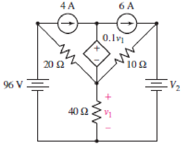
■ FIGURE 4.83
Expert Solution & Answer
Want to see the full answer?
Check out a sample textbook solution
Students have asked these similar questions
a) Apply nodal analysis to solve for Vx in the circuit of figure Ba.
Copyright © The McGraw-Hill Companies, Inc. Permission required for reproduction or display
2 A (4)
10 Ω
V
20 Ω
0.2Vx
Figure Ba
b) A battery has a short-circuit current of 20-A and an open-circuit voltage of 12-V. If
the battery is connected to an electric bulb of resistance 2-0, calculate the power
dissipated by the bulb.
+
6. a) Use the mesh-current method to write a complete set of equations that could be used to
solve this circuit. Do not simplify the circuit. Do not attempt to solve or simplify your
equations. Define all variables.
b) Compare the number of equations required using the node-voltage method and the mesh
current method, for this circuit. Which method requires fewer equations?
32[0]
24[Q]
28[Q]
11[O]ix
31[Q)
30[0]
| 2[V]
33[Q] i
34[Q]
35[0]
3[A]
38[0]
29[0]
10[O]i
4[V]
Vr
36[2]
37[0]
6[A]
5[V]
25[0]
Solve the given circuit (calculate all of the
voltage and the current variables) using
two methods.
a) Solve using mesh-current method.
b) Solve using node-voltage method.
R,
i,- 4i,
R,
R1 = 10 kQ
R2 = 20 kQ
R3 = 30 kQ
R4 = 40 kQ
R5 = 50 kQ
V6 = 20 V
V, = 4 V
Is = 1 A
V,
R,
R,
Chapter 4 Solutions
Loose Leaf for Engineering Circuit Analysis Format: Loose-leaf
Ch. 4.1 - For the circuit of Fig. 4.3, determine the nodal...Ch. 4.1 - For the circuit of Fig. 4.5, compute the voltage...Ch. 4.1 - For the circuit of Fig. 4.8, determine the nodal...Ch. 4.2 - For the circuit of Fig. 4.11, compute the voltage...Ch. 4.3 - Determine i1 and i2 in the circuit in Fig. 4.19....Ch. 4.3 - Determine i1 and i2 in the circuit of Fig 4.21....Ch. 4.3 - Determine i1 in the circuit of Fig. 4.24 if the...Ch. 4.4 - Determine the current i1 in the circuit of Fig....Ch. 4.4 - Determine v3 in the circuit of Fig. 4.28. FIGURE...Ch. 4 - Solve the following systems of equations: (a) 2v2 ...
Ch. 4 - (a) Solve the following system of equations:...Ch. 4 - (a) Solve the following system of equations:...Ch. 4 - Correct (and verify by running) the following...Ch. 4 - In the circuit of Fig. 4.35, determine the current...Ch. 4 - Calculate the power dissipated in the 1 resistor...Ch. 4 - For the circuit in Fig. 4.37, determine the value...Ch. 4 - With the assistance of nodal analysis, determine...Ch. 4 - Prob. 9ECh. 4 - For the circuit of Fig. 4.40, determine the value...Ch. 4 - Use nodal analysis to find vP in the circuit shown...Ch. 4 - Prob. 12ECh. 4 - Prob. 13ECh. 4 - Determine a numerical value for each nodal voltage...Ch. 4 - Prob. 15ECh. 4 - Using nodal analysis as appropriate, determine the...Ch. 4 - Prob. 17ECh. 4 - Determine the nodal voltages as labeled in Fig....Ch. 4 - Prob. 19ECh. 4 - Prob. 20ECh. 4 - Employing supernode/nodal analysis techniques as...Ch. 4 - Prob. 22ECh. 4 - Prob. 23ECh. 4 - Prob. 24ECh. 4 - Repeat Exercise 23 for the case where the 12 V...Ch. 4 - Prob. 26ECh. 4 - Prob. 27ECh. 4 - Determine the value of k that will result in vx...Ch. 4 - Prob. 29ECh. 4 - Prob. 30ECh. 4 - Prob. 31ECh. 4 - Determine the currents flowing out of the positive...Ch. 4 - Obtain numerical values for the two mesh currents...Ch. 4 - Use mesh analysis as appropriate to determine the...Ch. 4 - Prob. 35ECh. 4 - Prob. 36ECh. 4 - Find the unknown voltage vx in the circuit in Fig....Ch. 4 - Prob. 38ECh. 4 - Prob. 39ECh. 4 - Determine the power dissipated in the 4 resistor...Ch. 4 - (a) Employ mesh analysis to determine the power...Ch. 4 - Define three clockwise mesh currents for the...Ch. 4 - Prob. 43ECh. 4 - Prob. 44ECh. 4 - Prob. 45ECh. 4 - Prob. 46ECh. 4 - Prob. 47ECh. 4 - Prob. 48ECh. 4 - Prob. 49ECh. 4 - Prob. 50ECh. 4 - Prob. 51ECh. 4 - Prob. 52ECh. 4 - For the circuit represented schematically in Fig....Ch. 4 - The circuit of Fig. 4.80 is modified such that the...Ch. 4 - The circuit of Fig. 4.81 contains three sources....Ch. 4 - Solve for the voltage vx as labeled in the circuit...Ch. 4 - Consider the five-source circuit of Fig. 4.83....Ch. 4 - Replace the dependent voltage source in the...Ch. 4 - After studying the circuit of Fig. 4.84, determine...Ch. 4 - Prob. 60ECh. 4 - Employ LTspice (or similar CAD tool) to verify the...Ch. 4 - Employ LTspice (or similar CAD tool) to verify the...Ch. 4 - Employ LTspice (or similar CAD tool) to verify the...Ch. 4 - Verify numerical values for each nodal voltage in...Ch. 4 - Prob. 65ECh. 4 - Prob. 66ECh. 4 - Prob. 67ECh. 4 - Prob. 68ECh. 4 - Prob. 69ECh. 4 - (a) Under what circumstances does the presence of...Ch. 4 - Referring to Fig. 4.88, (a) determine whether...Ch. 4 - Consider the LED circuit containing a red, green,...Ch. 4 - The LED circuit in Fig. 4.89 is used to mix colors...Ch. 4 - A light-sensing circuit is in Fig. 4.90, including...Ch. 4 - Use SPICE to analyze the circuit in Exercise 74 by...
Additional Engineering Textbook Solutions
Find more solutions based on key concepts
What is the color code for a 365- five-band precision resistor with a tolerance of 5 percent?
ELECTRICITY FOR TRADES (LOOSELEAF)
Design an ideal inverting op-amp circuit such that the voltage gain is Av=25 . The maximum current in any resis...
Microelectronics: Circuit Analysis and Design
Does the severity of an electric shock increase ordecrease with eh of the following changes? a. A decrease in t...
Electric Motors and Control Systems
How many coulombs do 93.8 1016 electrons represent?
Principles Of Electric Circuits
The voltage source of the circuit shown in Fig. P1.29 is given by s(t)=25cos(4104t45)(V). Obtain an expression ...
Fundamentals of Applied Electromagnetics (7th Edition)
Find I0 and I1 in the circuit in Fig.P2.12.
Basic Engineering Circuit Analysis
Knowledge Booster


Learn more about
Need a deep-dive on the concept behind this application? Look no further. Learn more about this topic, electrical-engineering and related others by exploring similar questions and additional content below.Similar questions
- Solve step by steo a) and b) please a) Determine Vs and Rs from a voltage source equivalent to a current source with Is = 500 mA and Rs = 600 Ω b) Determine Is and Rs of a current source equivalent to a voltage source with Vs = 13V and Rs = 10Ωarrow_forwardA network connected between terminals a and b consists of two parallel combinations that are in series. The first parallel combination is composed of a 10-Ω resistor and a 15-Ω resistor. The second parallel combination is composed of a 14-Ω resistor and a 35-Ω resistor. a) Draw the network. b) Determine its equivalent resistance.arrow_forwardDesign an ohmmeter with Voltage, V = 6 V, If Rs can change from 0 Ω to 1500 Ω, galvanometer(ammeter) full scale current is 1mA. What is the minimum and maximum resistance that we can measure? (N.B.: write your answer like Rmin-Rmax. For examle 100 Ω -1000 Ω )arrow_forward
- Figure Q4(a) shows a two-port network circuit. (1) (ii) Calculate the admittance parameters of the circuit. Based on the answers in part Q4(a)(i), deduce the equivalent circuit for the circuit in Figure Q4(a). I1 V₁ 1092 W 12.5Ω W MM² 5Ω W 5Ω Figure Q4(a) 12 + V₂arrow_forward2) (ch 4 #4 from Nise) Consider a single loop circuit consisting of a 5V de battery, a 1.8 ohm resistor, and a 0.79F capacitor. If the circuit is completed (think closing a switch) at t=0, find the capacitor voltage (in other words, find ve(t) as you did in DS1) in the network as a function of time. (1) Use KVL to find the equation of the circuit in terms of vc. (2) Take the Laplace transform of the equation. (3) Solve this equation for V (s) then take the inverse Laplace transform to get ve (t). Also find the time constant, rise time, and settling time for the capacitor voltage.arrow_forwardNOTE: Solve this as soon as possible, I need this urgently. Determine the current I, in the circuit below using Nodal analysis 4 mA 2 kn 2 mA 1 kn ; 1 kn 6 mAarrow_forward
- SUPERPOSITION THEOREM( NEED NEAT HANDWRITTEN SOLUTION ONLY OTHERWISE DOWNVOTE).arrow_forwardTHEVENINS theorem( NEED NEAT HANDWRITTEN SOLUTION ONLY OTHERWISE DOWNVOTE).arrow_forwardConsider the circuit shown in the figure, where E, = 22.7 v, E, = 10.3 V, and R = 13.0 Q. (Due to the nature of this problem, do not use rounded intermediate values in your calculations-including answers submitted in WebAssign.) 28.0 N + E2 12.0 N I+ (a) What is the current (in A) in each resistor? A = I2 A %3D I3 A (b) What is the power (in W) delivered to each resistor? P1 %3D P2 w W (c) What is the total power (in W) supplied by both batteries? (d) What is the relationship between the total power supplied by the batteries and the power delivered to each resistor? The total power supplied by the batteries is equal to the sum of the power delivered to each resistor. The total power supplied by the batteries is less than the sum of the power delivered to each resistor. The total power supplied by the batteries is greater than the sum of the power delivered to each resistor.arrow_forward
- (a) Use the source transformation technique to solve V, in the circuit of Figure Q4(a). 30 2 40 2 10 2 30 Ω 15 V 20 V Figure Q4(a) wwarrow_forwardQ4 (a) Figure Q4(a) shows a two-port network circuit. (i) (ii) Calculate the admittance parameters of the circuit. Based on the answers in part Q4(a)(i), deduce the equivalent circuit for the circuit in Figure Q4(a). V₁ ö 1092 W 12.5Ω W m 552 W 552 Figure Q4(a) 12 V₂arrow_forwardSUPERPOSITION THEOREM ALONE( NEED NEAT HANDWRITTEN SOLUTION ONLY OTHERWISE DOWNVOTE).arrow_forward
arrow_back_ios
SEE MORE QUESTIONS
arrow_forward_ios
Recommended textbooks for you
 Introductory Circuit Analysis (13th Edition)Electrical EngineeringISBN:9780133923605Author:Robert L. BoylestadPublisher:PEARSON
 Delmar's Standard Textbook Of ElectricityElectrical EngineeringISBN:9781337900348Author:Stephen L. HermanPublisher:Cengage Learning
 Programmable Logic ControllersElectrical EngineeringISBN:9780073373843Author:Frank D. PetruzellaPublisher:McGraw-Hill Education
 Fundamentals of Electric CircuitsElectrical EngineeringISBN:9780078028229Author:Charles K Alexander, Matthew SadikuPublisher:McGraw-Hill Education
 Electric Circuits. (11th Edition)Electrical EngineeringISBN:9780134746968Author:James W. Nilsson, Susan RiedelPublisher:PEARSON
 Engineering ElectromagneticsElectrical EngineeringISBN:9780078028151Author:Hayt, William H. (william Hart), Jr, BUCK, John A.Publisher:Mcgraw-hill Education,
Introductory Circuit Analysis (13th Edition)
Electrical Engineering
ISBN:9780133923605
Author:Robert L. Boylestad
Publisher:PEARSON
Delmar's Standard Textbook Of Electricity
Electrical Engineering
ISBN:9781337900348
Author:Stephen L. Herman
Publisher:Cengage Learning
Programmable Logic Controllers
Electrical Engineering
ISBN:9780073373843
Author:Frank D. Petruzella
Publisher:McGraw-Hill Education
Fundamentals of Electric Circuits
Electrical Engineering
ISBN:9780078028229
Author:Charles K Alexander, Matthew Sadiku
Publisher:McGraw-Hill Education
Electric Circuits. (11th Edition)
Electrical Engineering
ISBN:9780134746968
Author:James W. Nilsson, Susan Riedel
Publisher:PEARSON
Engineering Electromagnetics
Electrical Engineering
ISBN:9780078028151
Author:Hayt, William H. (william Hart), Jr, BUCK, John A.
Publisher:Mcgraw-hill Education,
[1.2] 8086 Microprocessor Architecture; Author: ThinkX Academy;https://www.youtube.com/watch?v=XX9rDGTBGgQ;License: Standard Youtube License