
Loose Leaf for Engineering Circuit Analysis Format: Loose-leaf
9th Edition
ISBN: 9781259989452
Author: Hayt
Publisher: Mcgraw Hill Publishers
expand_more
expand_more
format_list_bulleted
Concept explainers
Videos
Textbook Question
Chapter 4.4, Problem 9P
Determine the current i1 in the circuit of Fig. 4.26.
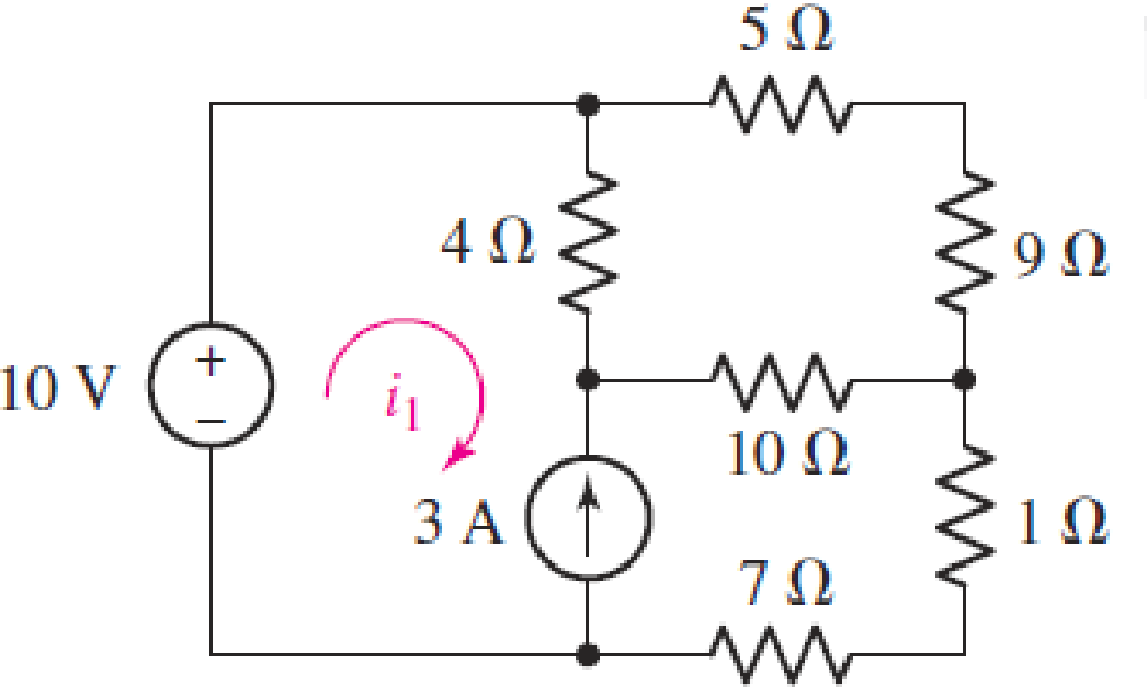
FIGURE 4.25
Expert Solution & Answer
Want to see the full answer?
Check out a sample textbook solution
Students have asked these similar questions
(a)
Simplify the circuit shown in Figure Q4 (a) into single voltage source by
applying source transformation and determine the current, io.
3 A
6 A
20 V
Figure Q4 (a)
a. Using KVL, complete the working equations for the clipping circuits shown in Fig. 4.11 for both positive and
negative half-cycles of the input.
Simple Parallel Clippers (ldeal Diodles)
Biased Parallel Clippers tldeal Diodes)
Figure 4.11 Clipping Circuits (Parallel)
4.70 An automobile battery, when connected to a car
radio, provides 12.5 V to the radio. When connected
to a set of headlights, it provides 11.7 V to the head-
lights. Assume the radio can be modeled as a 6.25 N
resistor and the headlights can be modeled as a
0.65 N resistor. What are the Thévenin and Norton
equivalents for the battery?
Chapter 4 Solutions
Loose Leaf for Engineering Circuit Analysis Format: Loose-leaf
Ch. 4.1 - For the circuit of Fig. 4.3, determine the nodal...Ch. 4.1 - For the circuit of Fig. 4.5, compute the voltage...Ch. 4.1 - For the circuit of Fig. 4.8, determine the nodal...Ch. 4.2 - For the circuit of Fig. 4.11, compute the voltage...Ch. 4.3 - Determine i1 and i2 in the circuit in Fig. 4.19....Ch. 4.3 - Determine i1 and i2 in the circuit of Fig 4.21....Ch. 4.3 - Determine i1 in the circuit of Fig. 4.24 if the...Ch. 4.4 - Determine the current i1 in the circuit of Fig....Ch. 4.4 - Determine v3 in the circuit of Fig. 4.28. FIGURE...Ch. 4 - Solve the following systems of equations: (a) 2v2 ...
Ch. 4 - (a) Solve the following system of equations:...Ch. 4 - (a) Solve the following system of equations:...Ch. 4 - Correct (and verify by running) the following...Ch. 4 - In the circuit of Fig. 4.35, determine the current...Ch. 4 - Calculate the power dissipated in the 1 resistor...Ch. 4 - For the circuit in Fig. 4.37, determine the value...Ch. 4 - With the assistance of nodal analysis, determine...Ch. 4 - Prob. 9ECh. 4 - For the circuit of Fig. 4.40, determine the value...Ch. 4 - Use nodal analysis to find vP in the circuit shown...Ch. 4 - Prob. 12ECh. 4 - Prob. 13ECh. 4 - Determine a numerical value for each nodal voltage...Ch. 4 - Prob. 15ECh. 4 - Using nodal analysis as appropriate, determine the...Ch. 4 - Prob. 17ECh. 4 - Determine the nodal voltages as labeled in Fig....Ch. 4 - Prob. 19ECh. 4 - Prob. 20ECh. 4 - Employing supernode/nodal analysis techniques as...Ch. 4 - Prob. 22ECh. 4 - Prob. 23ECh. 4 - Prob. 24ECh. 4 - Repeat Exercise 23 for the case where the 12 V...Ch. 4 - Prob. 26ECh. 4 - Prob. 27ECh. 4 - Determine the value of k that will result in vx...Ch. 4 - Prob. 29ECh. 4 - Prob. 30ECh. 4 - Prob. 31ECh. 4 - Determine the currents flowing out of the positive...Ch. 4 - Obtain numerical values for the two mesh currents...Ch. 4 - Use mesh analysis as appropriate to determine the...Ch. 4 - Prob. 35ECh. 4 - Prob. 36ECh. 4 - Find the unknown voltage vx in the circuit in Fig....Ch. 4 - Prob. 38ECh. 4 - Prob. 39ECh. 4 - Determine the power dissipated in the 4 resistor...Ch. 4 - (a) Employ mesh analysis to determine the power...Ch. 4 - Define three clockwise mesh currents for the...Ch. 4 - Prob. 43ECh. 4 - Prob. 44ECh. 4 - Prob. 45ECh. 4 - Prob. 46ECh. 4 - Prob. 47ECh. 4 - Prob. 48ECh. 4 - Prob. 49ECh. 4 - Prob. 50ECh. 4 - Prob. 51ECh. 4 - Prob. 52ECh. 4 - For the circuit represented schematically in Fig....Ch. 4 - The circuit of Fig. 4.80 is modified such that the...Ch. 4 - The circuit of Fig. 4.81 contains three sources....Ch. 4 - Solve for the voltage vx as labeled in the circuit...Ch. 4 - Consider the five-source circuit of Fig. 4.83....Ch. 4 - Replace the dependent voltage source in the...Ch. 4 - After studying the circuit of Fig. 4.84, determine...Ch. 4 - Prob. 60ECh. 4 - Employ LTspice (or similar CAD tool) to verify the...Ch. 4 - Employ LTspice (or similar CAD tool) to verify the...Ch. 4 - Employ LTspice (or similar CAD tool) to verify the...Ch. 4 - Verify numerical values for each nodal voltage in...Ch. 4 - Prob. 65ECh. 4 - Prob. 66ECh. 4 - Prob. 67ECh. 4 - Prob. 68ECh. 4 - Prob. 69ECh. 4 - (a) Under what circumstances does the presence of...Ch. 4 - Referring to Fig. 4.88, (a) determine whether...Ch. 4 - Consider the LED circuit containing a red, green,...Ch. 4 - The LED circuit in Fig. 4.89 is used to mix colors...Ch. 4 - A light-sensing circuit is in Fig. 4.90, including...Ch. 4 - Use SPICE to analyze the circuit in Exercise 74 by...
Knowledge Booster


Learn more about
Need a deep-dive on the concept behind this application? Look no further. Learn more about this topic, electrical-engineering and related others by exploring similar questions and additional content below.Similar questions
- 4.1 Find a Thévenin equivalent for the circuit shown with respect the 6 resistor. Use the Thévenin equivalent to find the current in the 6 2 resistor. If the 6 2 resistor were replaced with an 8 V source with positive terminal at the right, what would be the current in the source? 5 ohm w 40V 5 ohm 3 ohm 6 ohm ww 4 ohm 8 ohmarrow_forwardAn attenuator is an interface circuit that reduces the voltage level without changing the output resistance. (a) By specifying R, and R, of the interface circuit in Fig. 4.150, design an attenuator that will meet the following requirements: V. 0.125, Vg Rea = RTh = Rg = 100 N (b) Using the interface designed in part (a), calculate the current through a load of R1 = 50 N when V = 12 V. R, Rp RL Load Attenuator Reg In part (a) determine the values of Rs and RP. ww wwwarrow_forwardQ5 Draw the output voltage waveform for each circuit in Fig. 4.30 with respect the input. Show voltage levels. +1 V +1 V 0- -I V +2 V Vunmuy = 18 V Vrtmna = 110 V %3D -2 V (a) (b)arrow_forward
- QUESTION 2 Find Rth with respect to the terminals a,b for the circuit in Ohms. Figure P4.64 10 Ω 60 V www 40 Ω 8 Ω www a barrow_forwardQ4/ A) For the circuit shown below, calculate the current i, the conductance G, and the power P. 30 V (+ 5 k2arrow_forwardD LMH_chapter2-part2-homework. X + O File | C:/Users/DELL/Downloads/LMH_chapter2-part2-homework.pdf D Page view A Read aloud V Draw E Highlight O Erase 3 of 15 HW2 Use superposition to solve for v in the circuit of Fig. 4.87. 2Ω 6 A 4 A 8Ω 4ix 11:00 PM O Type here to search A a O 4) E ENG 3/22/2021arrow_forward
- Obtain the value of the rated current i10 in the circuit of figure 4.80arrow_forward4. Again assume each channel of our power supply can provide 30 V and we want to run a 60 V hair dryer motor. So, we again put the two channels in series for double the voltage. But, if you try this with a non-isolated supply, bad things will happen. Don't do that. The following depicts a circuit where internally the supplies have a common ground (i.e., they are not isolated). Non-Isolated Power Supply Droop2 ww 1mQ Channel2 30V 3.3A max Channel1 30V 3.3A max Droop1 1mQ I I I 1 I Red 1 I 1 Black Red Black JumperCable 26mQ 15A max Motor 1200 Needs -60V (a) Show that the current through the jumper cable will greatly exceed its current rating (which, as shown in the schematic, is 15 A). If this happens for more than a very short time, it will melt. (b) Show that the current through Channell greatly exceeds its maximum current rating. If the short circuit protection circuitry doesnt activate quickly, you will fry your power supply. Hint: You can redraw the circuit in a manner similar to…arrow_forward4.47.3 In the circuit shown in the image below, if R1 = 38 Q, R2 = 37 Q, and 1 A, determine the Norton current IN (in A) for its Norton equivalent circuit observed = 1.9 between terminals a and b. R2 R1 201v o b Please pay attention: the numbers may change since they are randomized. Your answer should keep 1 place after the decimal point. Your Answer: Answerarrow_forward
- Use the principle of superposition to find v, in the circuit shown in Figure 4. 22i, < sv(?) A 20K0 varrow_forwardSubject:Circuits IShow your solutions help me please so that i can learn tooarrow_forwardThe resistance of each brake light bulb on an automobile is 4.9 . Use the fact that cars have 12-V electrical systems to compute the current that flows in each bulb if they are connected in series. ( for simplicity, assume that the circuit is only composed of one brake light bulb and the car battery) Aarrow_forward
arrow_back_ios
SEE MORE QUESTIONS
arrow_forward_ios
Recommended textbooks for you
 Introductory Circuit Analysis (13th Edition)Electrical EngineeringISBN:9780133923605Author:Robert L. BoylestadPublisher:PEARSON
 Delmar's Standard Textbook Of ElectricityElectrical EngineeringISBN:9781337900348Author:Stephen L. HermanPublisher:Cengage Learning
 Programmable Logic ControllersElectrical EngineeringISBN:9780073373843Author:Frank D. PetruzellaPublisher:McGraw-Hill Education
 Fundamentals of Electric CircuitsElectrical EngineeringISBN:9780078028229Author:Charles K Alexander, Matthew SadikuPublisher:McGraw-Hill Education
 Electric Circuits. (11th Edition)Electrical EngineeringISBN:9780134746968Author:James W. Nilsson, Susan RiedelPublisher:PEARSON
 Engineering ElectromagneticsElectrical EngineeringISBN:9780078028151Author:Hayt, William H. (william Hart), Jr, BUCK, John A.Publisher:Mcgraw-hill Education,
Introductory Circuit Analysis (13th Edition)
Electrical Engineering
ISBN:9780133923605
Author:Robert L. Boylestad
Publisher:PEARSON
Delmar's Standard Textbook Of Electricity
Electrical Engineering
ISBN:9781337900348
Author:Stephen L. Herman
Publisher:Cengage Learning
Programmable Logic Controllers
Electrical Engineering
ISBN:9780073373843
Author:Frank D. Petruzella
Publisher:McGraw-Hill Education
Fundamentals of Electric Circuits
Electrical Engineering
ISBN:9780078028229
Author:Charles K Alexander, Matthew Sadiku
Publisher:McGraw-Hill Education
Electric Circuits. (11th Edition)
Electrical Engineering
ISBN:9780134746968
Author:James W. Nilsson, Susan Riedel
Publisher:PEARSON
Engineering Electromagnetics
Electrical Engineering
ISBN:9780078028151
Author:Hayt, William H. (william Hart), Jr, BUCK, John A.
Publisher:Mcgraw-hill Education,
Norton's Theorem and Thevenin's Theorem - Electrical Circuit Analysis; Author: The Organic Chemistry Tutor;https://www.youtube.com/watch?v=-kkvqr1wSwA;License: Standard Youtube License